
Device and Method of Determining the Force Required to Remove a Projectile from an Ammunition Cartridge

a technology of projectile removal and ammunition cartridge, which is applied in the direction of measurement devices, force/torque/work measurement devices, instruments, etc., can solve the problems of brass ammunition cartridge removal devices developed for brass ammunition cartridges and not applicable to polymer cartridges, so as to reduce the inner diameter, reduce the chamber diameter, and reduce the inner diameter

Active Publication Date: 2019-08-15
TRUE VELOCITY IP HLDG LLC
View PDF0 Cites 65 Cited by
  • Summary
  • Abstract
  • Description
  • Claims
  • Application Information

AI Technical Summary

Benefits of technology

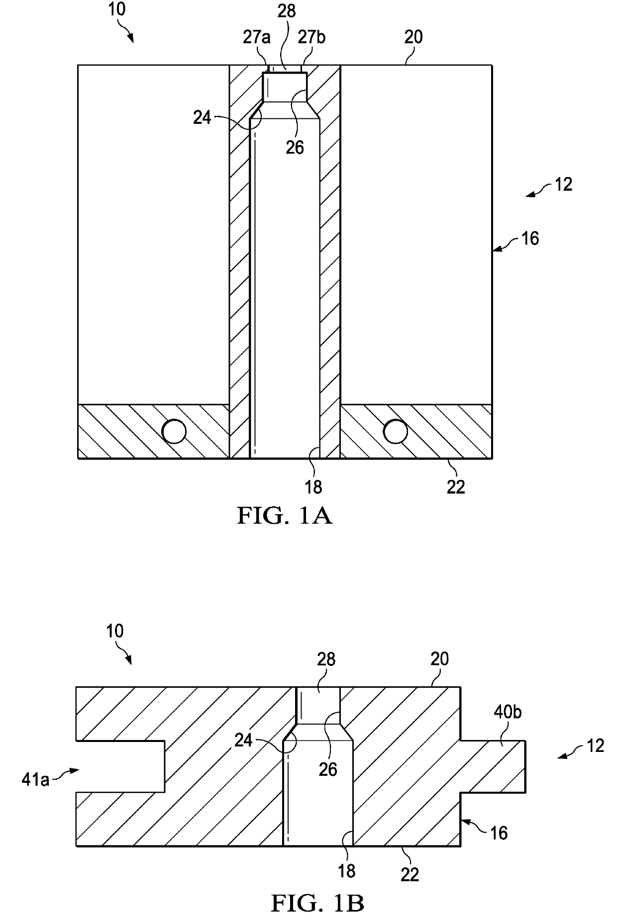
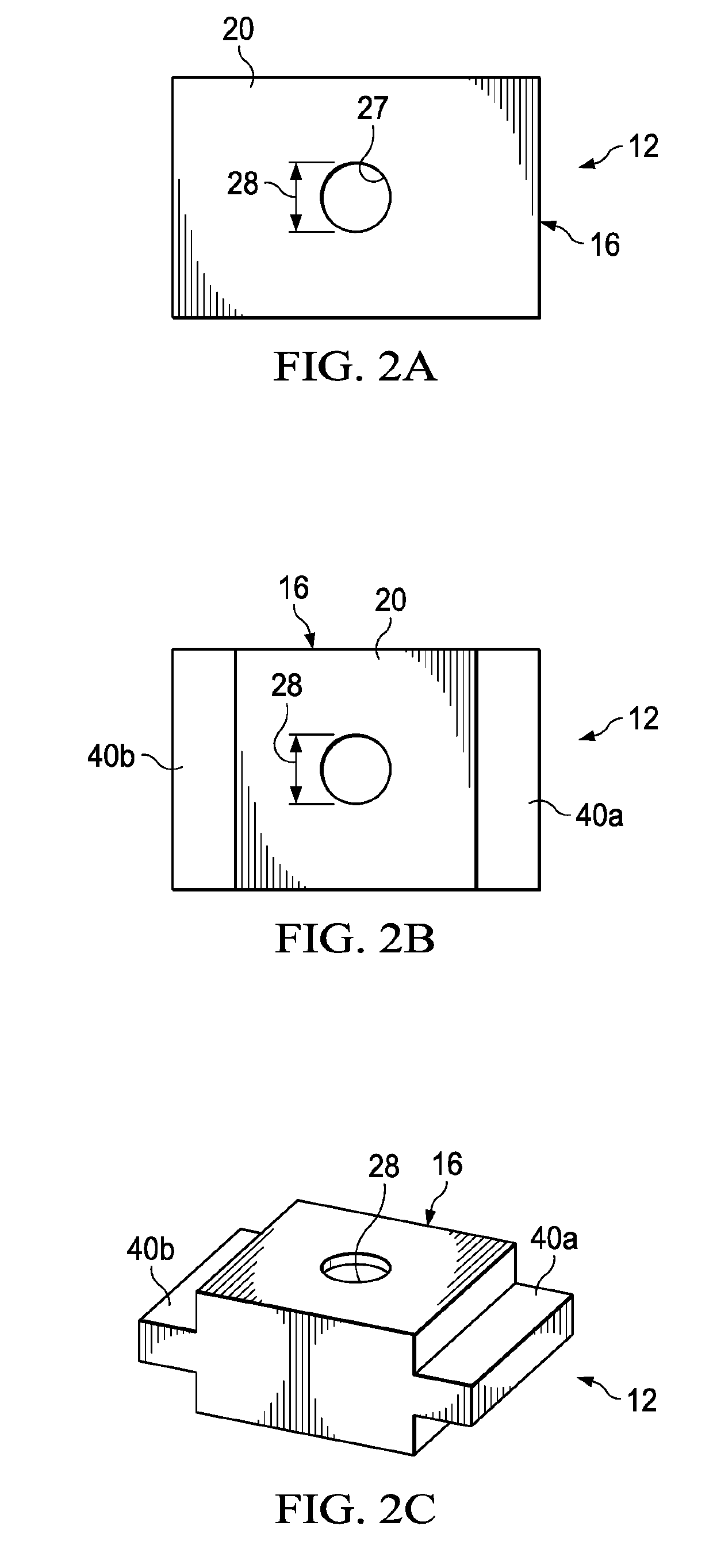
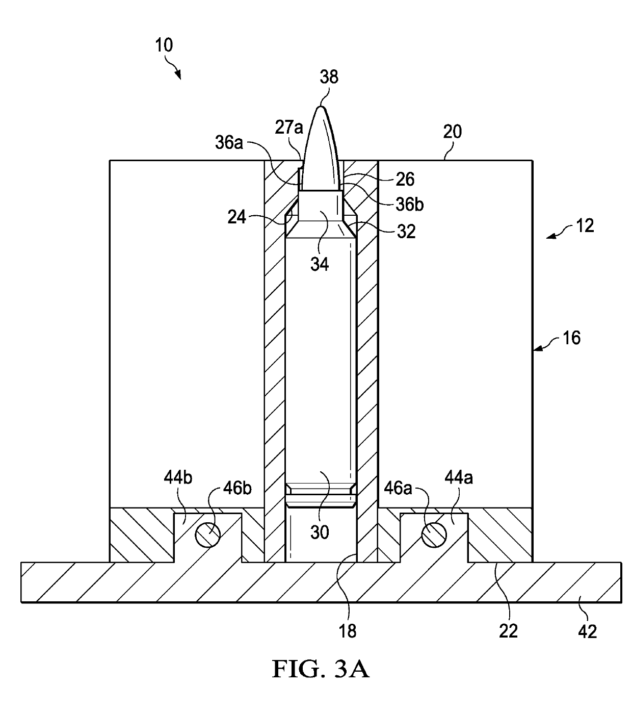
The present invention provides a device and method to determine the force required to remove a bullet from an ammunition cartridge. This device includes a chamber housing with a central bore that matches the profile of an ammunition cartridge and a frustconical shoulder to reduce the chamber diameter. The device also includes a bullet clamp to secure the bullet and a cartridge retention lip to resist the force. The device can be attached to a testing device and the force required to remove the bullet can be measured. The invention provides a means to ensure consistent quality control and to compare different types of ammunition.

Problems solved by technology

However current bullet removal devices are developed for brass ammunition cartridges and are not applicable to polymer cartridges given the unique properties of polymer relative to brass.

Method used


Image

  • Device and Method of Determining the Force Required to Remove a Projectile from an Ammunition Cartridge
  • Device and Method of Determining the Force Required to Remove a Projectile from an Ammunition Cartridge
  • Device and Method of Determining the Force Required to Remove a Projectile from an Ammunition Cartridge

Examples


Embodiment Construction

[0018]While the making and using of various embodiments of the present invention are discussed in detail below, it should be appreciated that the present invention provides many applicable inventive concepts that can be embodied in a wide variety of specific contexts. The specific embodiments discussed herein are merely illustrative of specific ways to make and use the invention and do not delimit the scope of the invention.

[0019]As used herein, the term “ammunition”, “ammunition article”, “munition”, and “munition article” as used herein may be used interchangeably to refer to a complete, assembled round or cartridge of that is ready to be loaded into a firearm and fired, including cap, casing, propellant, projectile, etc. Ammunition may be a live round fitted with a projectile, or a blank round with no projectile and may also be other types such as non-lethal rounds, rounds containing rubber bullets, rounds containing multiple projectiles (shot), tracer rounds, and rounds containi...


PUM


Abstract

The present invention includes a device for determining the force necessary for the separation of a bullet from an ammunition cartridge comprising a chamber housing having central bore extending from a lower housing end to an upper housing end and terminating at a upper aperture, wherein the central bore comprises a chamber diameter adapted to accept an ammunition cartridge and that the bullet partially extends from the upper aperture; a frustaconical shape shoulder in the central bore at the upper housing end to reduce the chamber diameter to mate to an ammunition cartridge shoulder; a neck that connects the upper aperture to the frustaconical shape shoulder adapted to accept an ammunition cartridge neck; a cartridge retention lip within the upper aperture adapted to contact an ammunition cartridge bullet aperture; a chamber mount adapted to connect the chamber housing and a testing device; a bullet securing device comprising a bullet securing end to secure the bullet and a bullet securing device mount adapted to connect to the testing device; a moving mechanism to move the bullet securing device away from the chamber housing; a sensor in communication with the moving mechanism to measure a force exerted by the moving mechanism; and a display in communication with the sensor to display and or record the force.

Description

CROSS-REFERENCE TO RELATED APPLICATIONS[0001]This application claims priority based on U.S. Provisional Application No. 62 / 630,515, filed Feb. 14, 2018. The contents of which is incorporated by reference in its entirety.TECHNICAL FIELD OF THE INVENTION[0002]The present invention relates in general to the field of ammunition production and certification, specifically to new and improved devices and methods for certification and standardization of ammunition.STATEMENT OF FEDERALLY FUNDED RESEARCH[0003]None.INCORPORATION-BY-REFERENCE OF MATERIALS FILED ON COMPACT DISC[0004]None.BACKGROUND OF THE INVENTION[0005]During the process of loading ammunition cartridges, a projectile is inserted into a cartridge and secured therein, generally by crimping the cartridge neck to the shank of the bullet securely enough that the bullet will not inadvertently separate or dislodged from the cartridge, but will be separated by the explosive force of the charge when fired. Current devices to separate a ...

Claims


Application Information

Patent Timeline
IPC IPC(8): F42B35/02F42B33/06
CPCF42B33/06F42B35/02F42B35/00G01L5/0033G01L5/0028
Inventor BURROW, LONNIESIUTS, TUCKER
Owner TRUE VELOCITY IP HLDG LLC
Learn More