
Flight device

a multi-rotor, flight technology, applied in the direction of remote controlled aircraft, unmanned aerial vehicles, vehicles, etc., can solve the problems of insurmountable accidents caused by single-axis uav motor failure, and achieve the effect of reducing device volume, improving lift force, and good lifting efficiency

Inactive Publication Date: 2019-08-15
CORETRONIC INTELLIGENT ROBOTICS CORP
View PDF0 Cites 11 Cited by
  • Summary
  • Abstract
  • Description
  • Claims
  • Application Information

AI Technical Summary

Benefits of technology

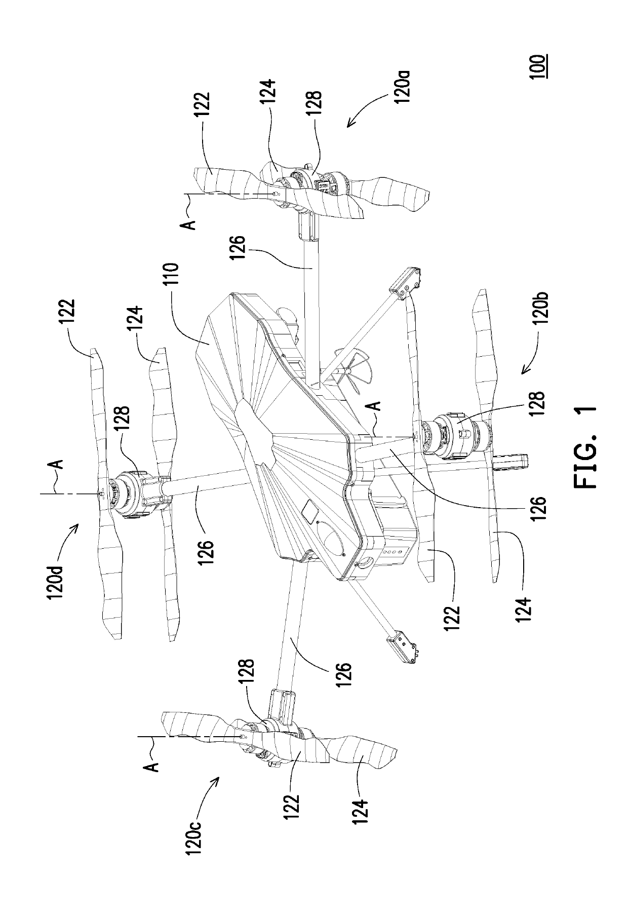
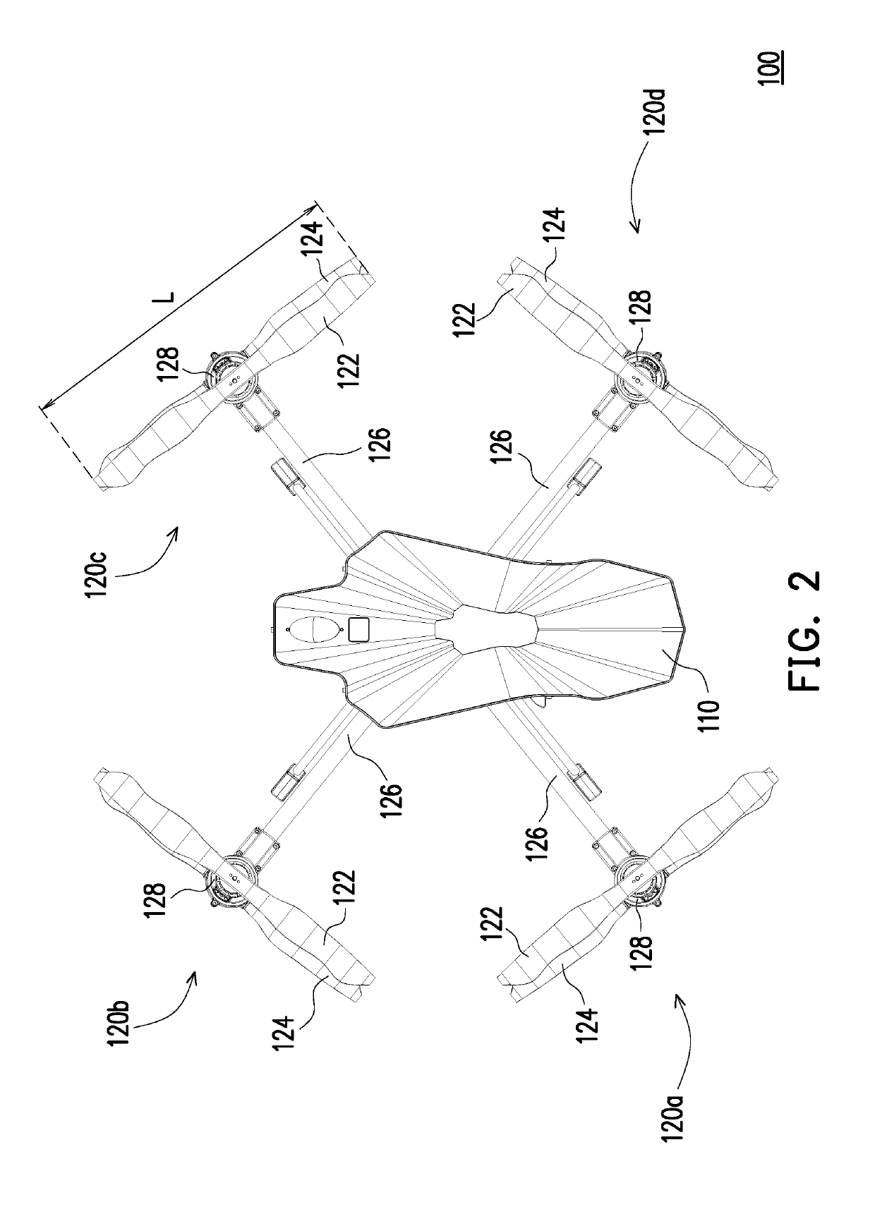
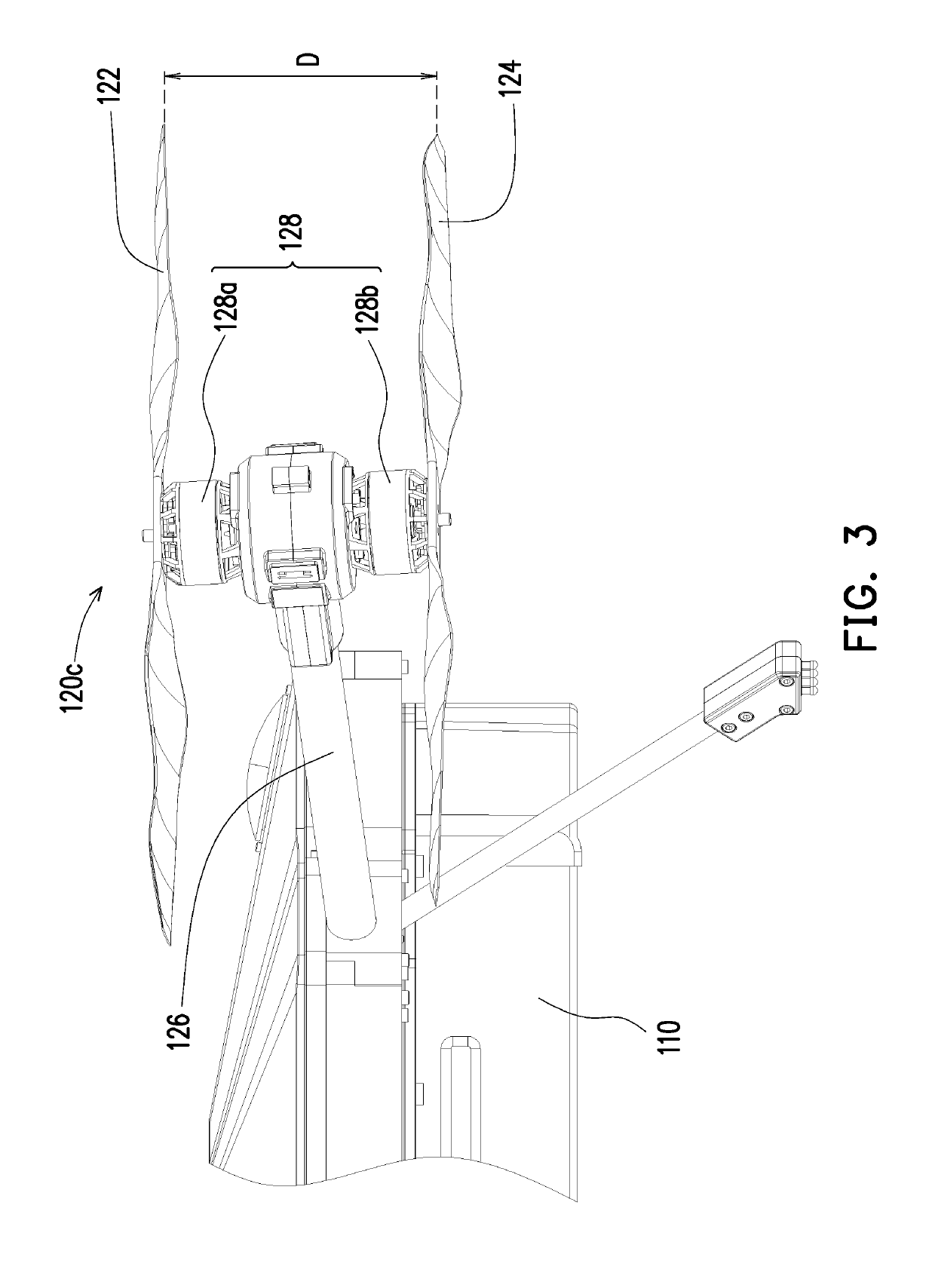
The invention is a flight device with better efficiency and reliability. It has multiple lift force providing modules with two propellers each, which increases the lift force and reduces the device size compared to conventional devices. The failure of a single propeller in a module can be compensated by adjusting the rotation speed of other propellers, which improves the overall performance of the device. This design allows for a larger lift force without adding additional blades or lift force providing modules. The overall torque of the device is balanced, making it more reliable in case of a propeller failure.

Problems solved by technology

However, accidents caused by failure of single-axis UAV motor have always been an insurmountable problem.

Method used


Image

  • Flight device
  • Flight device
  • Flight device

Examples


Embodiment Construction

[0015]In the following detailed description of the preferred embodiments, reference is made to the accompanying drawings which form a part hereof, and in which are shown by way of illustration specific embodiments in which the invention may be practiced. In this regard, directional terminology, such as “top,”“bottom,”“front,”“back,” etc., is used with reference to the orientation of the Figure(s) being described. The components of the present invention can be positioned in a number of different orientations. As such, the directional terminology is used for purposes of illustration and is in no way limiting. On the other hand, the drawings are only schematic and the sizes of components may be exaggerated for clarity. It is to be understood that other embodiments may be utilized and structural changes may be made without departing from the scope of the present invention. Also, it is to be understood that the phraseology and terminology used herein are for the purpose of description an...


PUM


Abstract

A flight device including a device main body and a plurality of lift force providing modules is provided. The lift force providing modules are connected to the device main body. Each of the lift force providing modules includes two propellers, and each of the propellers rotates to lift the device main body. Two propellers of each of the lift force providing modules may rotate around the same rotation axis. The flight device has an enhanced lift force and good efficiency in lifting, and the flight device has a reduced device volume and improved flight reliability.

Description

CROSS-REFERENCE TO RELATED APPLICATION[0001]This application claims the priority benefit of China application serial no. 201820257403.8, filed on Feb. 13, 2018. The entirety of the above-mentioned patent application is hereby incorporated by reference herein and made a part of this specification.BACKGROUND OF THE INVENTIONField of the Invention[0002]The invention relates to a flight device, and particularly relates to a multirotor flight device.Description of Related Art[0003]With the rapid development of technology, in recent years, major electronics companies have been actively engaged in the market of unmanned aircraft system (UAS), unmanned aerial vehicle (UAV), etc., which are originally applied in military fields and whose cost for development have been reduced. Among other applications of UAS / UAV, cargo / food delivery and sports photography have been fields of interest for major electronics companies to research. The UAV market is expected to bring a lot of job opportunities, ...

Claims


Application Information

Patent Timeline
Patent Type & Authority Applications(United States)
IPC IPC(8): B64C39/02B64C27/82
CPCB64C39/024B64C27/006B64C2201/027B64C2201/108B64U10/13B64U30/20
Inventor CHEN, YING-CHIEHLIN, SHIH-HANGHSIEH, CHI-TONG
Owner CORETRONIC INTELLIGENT ROBOTICS CORP
Learn More