
Deposition mask package and deposition mask packaging method

a technology of deposition mask and packaging method, which is applied in the direction of packaging, solid-state devices, metallic material coating process, etc., can solve the problems of plastic deformation of deposition mask, etc., to reduce the height of wall surface, and reduce the thickness of metal plate

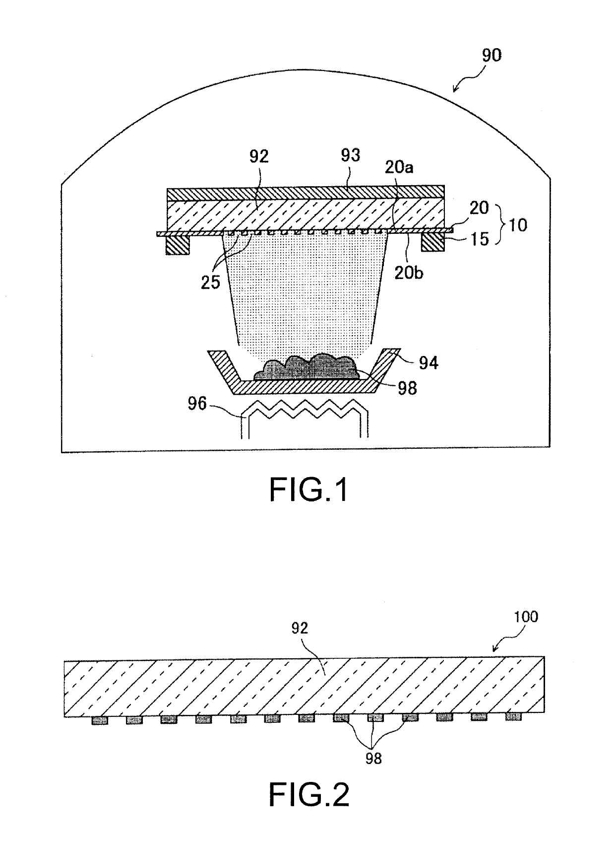
Active Publication Date: 2019-08-01
DAI NIPPON PRINTING CO LTD
View PDF5 Cites 6 Cited by
  • Summary
  • Abstract
  • Description
  • Claims
  • Application Information

AI Technical Summary

Benefits of technology

The patent text describes a solution to prevent deformation of a metal plate used in the manufacturing of a deposition mask for organic EL display devices. The solution involves reducing the thickness of the metal plate to reduce the amount of deposition materials adhering to the wall surface of the through-hole of the deposition mask, which can lower the height of the wall surface. This helps prevent deterioration of the light emission efficiency of the organic EL display device and ensures a thin deposition mask during transportation. The technical effect of the patent text is the prevention of plastic deformation of the deposition mask during transportation.

Problems solved by technology

Thus, there is a problem that the deposition mask taken out after unpacking may be plastically deformed.
In addition, there is a possibility that the deposition mask is plastically deformed even by an impact received during transportation.
In this case, there is a risk that a deposition mask may be plastically deformed at the time of taking out individual deposition masks because a through-hole of one of adjacent deposition masks and a through-hole of the other deposition mask are caught by each other.
However, when a temperature change occurs during transportation, a positional shift is generated due to a difference between a dimensional change caused by thermal expansion of the deposition mask and a dimensional change caused by thermal expansion of the interposed paper so that there is a problem that wrinkles or scratches are formed in the deposition mask.
That is, it is conceivable that deposition in the vicinity of the wall surface of the through-hole of the deposition mask becomes unstable.
As a result, the light emission efficiency of the organic EL display device deteriorates.

Method used


Image

  • Deposition mask package and deposition mask packaging method
  • Deposition mask package and deposition mask packaging method
  • Deposition mask package and deposition mask packaging method

Examples


examples

[0240]A transportation test of the deposition mask package 60 packing the deposition mask 20 was carried out using various interposed sheets 81 and states of the deposition masks 20 after transportation were confirmed.

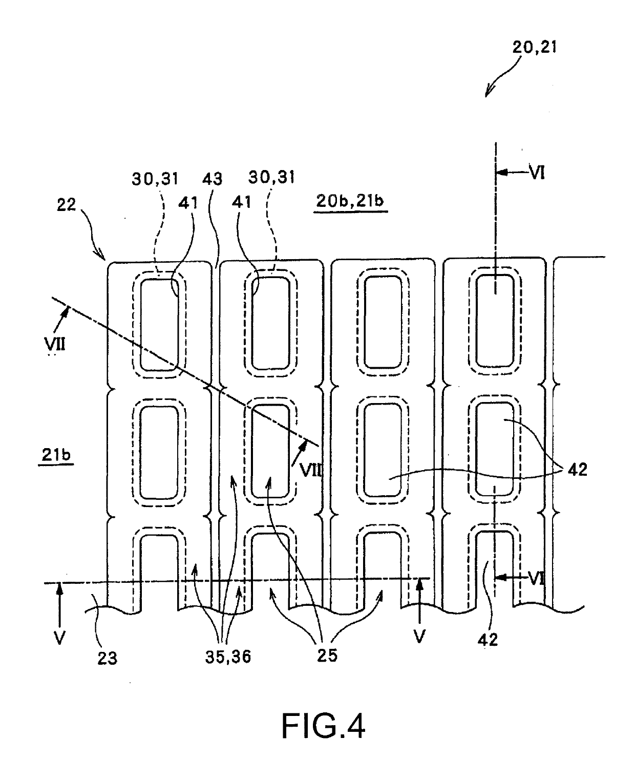
[0241]As the deposition masks 20 used in the transportation test, the deposition masks 20 having various thickness T0 were used as illustrated in FIG. 42. Each of the deposition masks 20 is the deposition mask 20 manufactured by the etching process illustrated in FIGS. 4 to 19. The deposition mask 20 was made of an invar material containing 36% by mass of nickel. In each of the deposition masks 20, the dimension W2 (see FIG. 33) in the width direction was set to 67 mm and the overall length D3 in the longitudinal direction was set to 850 mm.

[0242]As illustrated in FIG. 42, sheets made of various materials were used as the interposed sheet 81. More specifically, an invar material containing 36% by mass of nickel was used for the interposed sheet 81 as Example 1, a 42 al...


PUM

PropertyMeasurementUnit
thicknessaaaaaaaaaa
thicknessaaaaaaaaaa
widthaaaaaaaaaa

Abstract

A deposition mask package according to the present embodiment includes a receiving portion, a lid portion that faces the receiving portion, a deposition mask that is arranged between the receiving portion and the lid portion and has an effective region in which a plurality of through-holes is formed. The receiving portion has a first opposing surface facing the lid portion and a concave portion provided on the first opposing surface. The concave portion is covered by a first flexible film. The effective region of the deposition mask is arranged on the concave portion with the first flexible film interposed therebetween.

Description

CROSS-REFERENCE TO RELATED APPLICATIONS[0001]This application is a continuation of International Application No. PCT / JP2017 / 032938, filed Sep. 12, 2017.TECHNICAL FIELD[0002]The present embodiments relate to a deposition mask package obtained by packaging a deposition mask including a plurality of through-holes and a deposition mask packaging method.BACKGROUND ART[0003]In recent years, it is required for display devices used in portable devices, such as a smartphone and a tablet PC, to have high definition, for example, a pixel density of 400 ppi or higher. In addition, there is an increasing demand for adapting to ultra-high definition even with respect to the portable devices. In this case, it is required for the display devices to have a pixel density of, for example, 800 ppi or higher.[0004]Among the display devices, an organic EL display device has drawn attention due to good responsiveness, low power consumption, and high contrast. As a method of forming pixels of the organic E...

Claims


Application Information

Patent Timeline
Patent Type & Authority Applications(United States)
IPC IPC(8): H01L21/673B65D43/16B65D81/05B65D85/62B65D85/20C23C14/04C23F1/02H01L51/00H01L51/56
CPCH01L21/67359B65D43/16B65D81/05B65D85/62B65D85/20C23C14/042C23F1/02H01L51/001H01L51/0011H01L51/56B65D71/02B65D77/0406B65D79/00C23C14/24B65D77/04C23C14/04H05B33/10H05B33/14H10K71/166B32B15/012B32B15/18B32B2553/00B32B2037/246B32B2553/02B65B5/045B65B7/26B65B23/00B65B2220/16H01L25/00
Inventor IKENAGA, CHIKAOOIKE, TAKUMIMUKAIDA, TSUKASAWATANABE, TAKERU
Owner DAI NIPPON PRINTING CO LTD
Learn More