Method for operating a multi-frequency metal detector and multi-frequency metal detector

Active Publication Date: 2019-08-01
METTLER TOLEDO SAFELINE
View PDF2 Cites 1 Cited by
  • Summary
  • Abstract
  • Description
  • Claims
  • Application Information

AI Technical Summary

Benefits of technology

The metal detector described in this patent has a more efficient and compact multi-frequency transmitter that can be built at a lower cost. This allows for maximizing the coil current and producing high drive currents in the drive coil while keeping the currents in the transmitter unit low. The detector also includes a drive circuitry that can simplify the process of actuating the drive switches. The detector can directly supply the drive current to the drive coil, resulting in higher drive currents than currently achievable. Additionally, the detector includes an admittance unit that can actively match the frequency components of the drive current to the drive coil, improving the signal-to-noise ratio and sensitivity of the metal detector. This invention provides a versatility in the use of the multi-frequency drive current and the adjmtance unit, either independently or in combination with other methods or components.

Problems solved by technology

However, driving the coil system by a square wave (or a trapezoidal wave due to the inductance of the coil) generates a large number of relatively high energy harmonics compared with the conventional sinusoidal signal generated by a tuned circuit.
While one operating frequency may be suitable for one specific metal contaminant, the same frequency may not provide the desired results for other metal contaminants.
The multi-frequency transmitter must therefore be dimensioned and built accordingly with considerable costs.

Method used


Image

  • Method for operating a multi-frequency metal detector and multi-frequency metal detector
  • Method for operating a multi-frequency metal detector and multi-frequency metal detector
  • Method for operating a multi-frequency metal detector and multi-frequency metal detector

Examples


Embodiment Construction

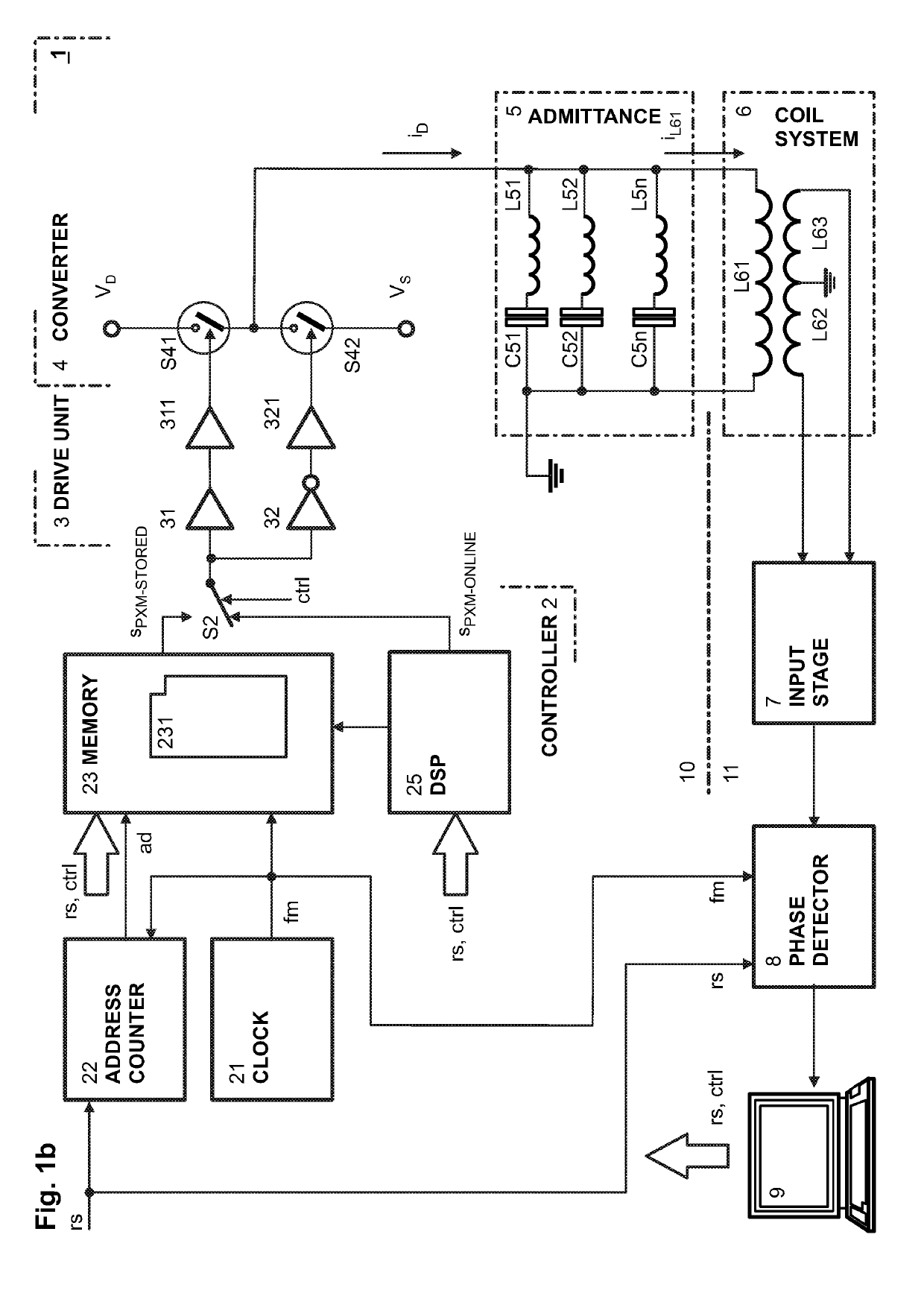
[0047]FIG. 1a shows a first embodiment of an inventive metal detector 1 that comprises a transmitter unit 10 and a receiver unit 11 and a balanced coil system 6 with a drive coil L61 connected to the output of the transmitter unit 10 and two detection coils L62 and L63 connected on one end to ground potential and with the other end to an input stage 7 of the receiver unit 11. In the input stage 7 the input signal is typically amplified and filtered and then forwarded to a phase detector 8. The phase detector 8 allows distinguishing between the phases of the signal components of different origin and obtaining information about the observed product and contaminants, if present. A typical phase detector, e.g. a frequency mixer or analogue multiplier circuit, generates two independent voltage signals which represent the in-phase and quadrature component provided by the input stage 7, and a reference signal fm provided by the transmitter unit 10. The output signal of the phase detector 8...


PUM


Abstract

A metal detector (1) has a drive coil (L61) and at least one detection coil (L62, L63) that detect fluctuations in a magnetic field generated by the drive coil, caused by metallic particles present in an inspected object. A multi-frequency transmitter unit (10) has a converter (4) with a plurality of drive switches (S41, S42; S43, S44) driven by a drive controller (2). The drive switches alternately conduct a drive current through the drive coil to generate an electromagnetic field with two or more different frequency components. A waveform of the drive current is determined, as is at least one pulse-modulated (PXM) signal corresponding to the determined waveform. The determined PXM-signal is determined online or is stored in a memory module (231; 232). The determined PXM-signal is generated and applied to control the drive switches. The drive current can be applied to the drive coil through an admittance unit (5).

Description

CROSS-REFERENCE TO RELATED APPLICATIONS[0001]This application claims priority to European Patent Application 18154719.1, filed on 1 Feb. 2018, which is incorporated by reference as if fully recited herein.TECHNICAL FIELD[0002]The invention relates to a method for operating a multi-frequency metal detector and to a multi-frequency metal detector operating according to this method.BACKGROUND ART[0003]As described in US published application 2012 / 0206138 A1, metal detectors are used to detect and reject unwanted metal contamination. When properly installed and operated, a metal detector will help reduce metal contamination and improving food safety. Most modern metal detectors utilise a search head comprising a coil system with a drive coil receiving a drive signal and generating an electromagnetic field in the product, and at least one detection coil arranged to detect fluctuations in the magnetic field caused by the presence of metallic particles in the product including ferrous, non...

Claims


Application Information

Patent Timeline
IPC IPC(8): G01V3/10H01F7/06
CPCG01V3/10H01F7/064G01V3/107
Inventor TAO, YANGKTISTIS, CHRISTOS
Owner METTLER TOLEDO SAFELINE
Why Eureka
Try Eureka