Gasket

a gasket and flange technology, applied in the field of gaskets, can solve the problems of difficult horizontal maintenance of the flatness of the flanges b>1/b> which are connection parts of the tubular body, complicated use conditions, etc., and achieve the effect of restoring force, improving sealing performance, and high bolting for

Pending Publication Date: 2019-08-01
LEE JONG CHUL
View PDF0 Cites 1 Cited by
  • Summary
  • Abstract
  • Description
  • Claims
  • Application Information

AI Technical Summary

Benefits of technology

[0038]A gasket according to an exemplary embodiment of the present invention has the following advantages.
[0039]First, the gasket may secure a higher bolting force and restoring force than those of other gaskets having the same size as the gasket. Thus, the sealing performance of the gasket is improved even at a high temperature and under a high pressure.
[0040]Second, a core spring may be easily fixed and attached through a C-ring end formed at a side of a kammprofile without an external jacket. Thus, production costs may be reduced by simplifying the structure of the gasket as described above. Furthermore, the restoring force of the gasket may be improved.
[0041]Thirdly, a load of a fastening bolt may be concentrated around peaks of a sawtooth member even under a low bolting pressure through the saw tooth member formed on upper and lower surfaces of the kammprofile. Thus, perfect sealing performance may be provided.
[0042]Fourthly, the C-ring end is formed at opposite sides of the kammprofile and thus the restoring force and sealing performance of the gasket are more improved.
[0043]Fifthly, the gasket includes an eyelet covering the C-ring end of the kammprofile and thus inner components of the gasket may be prevented from coming into direct contact with a fluid flowing through a pipe, thereby decreasing turbulence caused by the fluid.

Problems solved by technology

Originally, gaskets formed of paper, leather, or the like were used for simple purposes but recently, various shapes and materials of gaskets have been used as use conditions become complicated and severe.
In particular, when an operating condition of the plant is that heating and cooling should be continuously performed and thus a high-temperature and high-pressure fluid repeatedly flows inside tubular bodies 1, the flatness of flanges 2 which are connection parts of the tubular bodies 1 are difficult to perfectly horizontally maintain.

Method used


Image

  • Gasket
  • Gasket
  • Gasket

Examples


first embodiment

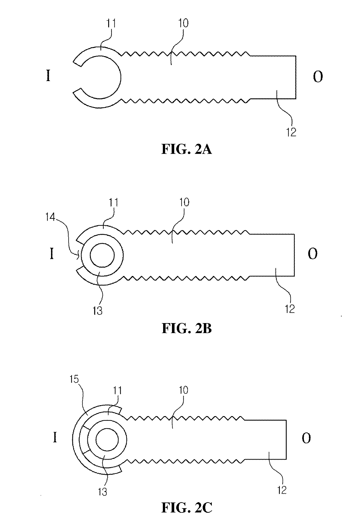
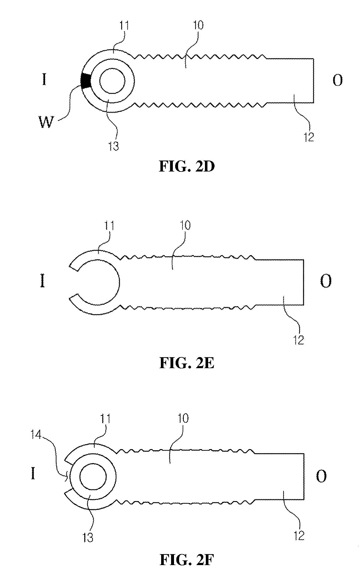
[0062]FIGS. 2A to 2F are diagrams illustrating a gasket according to the present invention and modified examples thereof.

[0063]As illustrated in FIG. 2A, the gasket according to the first embodiment of the present invention may include a kammprofile 10, a C-ring end 11 formed at an inner side (I) of the kammprofile 10, and an outer ring end 12 formed at an outer side (O) of the kammprofile 10. A sawtooth member may be formed on upper and lower surfaces of the kammprofile 10.

[0064]The sawtooth member may be manufactured by serration processing. The gasket according to the first embodiment of the present invention may concentrate a load of a fastening bolt around peaks of the sawtooth member under low bolting pressure through the sawtooth members on the upper and lower surfaces of the kammprofile 10, thereby maintaining perfect sealing performance even under the low bolting pressure.

[0065]The outer-ring end 12 formed at the outer side (O) of the kammprofile 10 may guide the gasket to ...

second embodiment

[0080]FIGS. 3A to 3D are diagrams illustrating a gasket according to the present invention and modified examples thereof.

[0081]As illustrated in FIG. 3A, the gasket according to the second embodiment of the present invention may include a kammprofile 10, a C-ring end 11 formed at an inner side (I) of the kammprofile 10, and an outer-ring end 12 formed on an outer side (O) of the kammprofile 10. A sawtooth member may be formed on upper and lower surfaces of the kammprofile 10.

[0082]A stopper 16 may be formed on at least a part of the upper and lower surfaces of the kammprofile 10.

[0083]A modification may be made to the gasket according to the second embodiment of the present invention as illustrated in FIG. 3B.

[0084]The gasket illustrated in FIG. 3B may further include a core spring 13 accommodated in a C-ring end 11 via an opening 14 of the C-ring end 11.

[0085]A modification may be also made to the gasket according to the second embodiment of the present invention as illustrated in ...

third embodiment

[0092]FIGS. 4A to 4C are diagrams illustrating a gasket according to the present invention and modified examples thereof.

[0093]As illustrated in FIG. 4A, the gasket according to the third embodiment of the present invention may include a convex type kammprofile 10 and a C-ring end 11 formed at an inner side (I) of the kammprofile 10.

[0094]Similar to the previous embodiments, sawteeth may be formed on upper and lower surfaces of the kammprofile 10 of the gasket according to the third embodiment.

[0095]A modification may be made to the gasket according to the third embodiment of the present invention as illustrated in FIG. 4B.

[0096]The gasket of FIG. 4B may further include a core spring 13 accommodated in a C-ring end 11 via an opening 14.

[0097]A modification may be also made to the gasket according to the third embodiment of the present invention as illustrated in FIG. 4C. The gasket of FIG. 4C may further include an eyelet 15 covering a C-ring end 11.


PUM


Abstract

Provided is a gasket, and more particularly, to a gasket including a C-ring end formed at at least one side of a kammprofile. According to the present invention, a higher bolting force and restoring force may be secured than those of other gaskets having the same size as the gasket. Furthermore, a core spring may be easily fixed and attached to the gasket through the C-ring end formed at the kammprofile without an external jacket. Accordingly, production costs may be decreased by simplifying the structure of the gasket as described above.

Description

TECHNICAL FIELD[0001]The present invention relates to a gasket, and more particularly, to a gasket including a C-ring end at at least one side of a kammprofile.BACKGROUND ART[0002]A gasket collectively refers to static seals coupled between fixed joined surfaces, such as joined surfaces of pressure vessels, pipe flanges, machines and equipment, via a bolt or the like to prevent leakage. Various shapes and materials of gaskets are used according to use conditions such as the type of a working fluid, pressure, temperature, etc.[0003]Originally, gaskets formed of paper, leather, or the like were used for simple purposes but recently, various shapes and materials of gaskets have been used as use conditions become complicated and severe.[0004]That is, a gasket is inserted between two tubular bodies to prevent a fluid from leaking through a gap between the tubular bodies. For example, the gasket is installed between flanges which are connection parts of a valve or tubular bodies, such as ...

Claims


Application Information

Patent Timeline
Patent Type & Authority Applications(United States)
IPC IPC(8): F16J15/08F16L17/06F16L23/18
CPCF16J15/08F16L17/06F16L23/18F16J15/0818F16L23/20F16J15/06F16L23/16
Inventor LEE, JONG CHUL
Owner LEE JONG CHUL
Why Eureka
Try Eureka