Method for Producing an Electronic Assembly, and Electronic Assembly, in particular for a Transmission Control Module

Active Publication Date: 2019-07-25
ROBERT BOSCH GMBH
View PDF2 Cites 1 Cited by
  • Summary
  • Abstract
  • Description
  • Claims
  • Application Information

AI Technical Summary

Benefits of technology

The present invention provides a method for producing an electronic assembly that is oil-tight, robust, and has a long service life. The method involves arranging a printed circuit board with a sealing material around it, adding a component, and connecting it to the circuit board. A covering material is then added to the sealing material and the component. The sealing material and covering material are then cured. This method simplifies the production process and allows for a more durable oil-tightness. The electronic assembly can be placed on the same reference surface as the electronics themselves.

Problems solved by technology

A disadvantage of this is that the transmission control module with the electronic assembly or the electronic assembly is less stable and robust and involves high production costs and great production effort.
Moreover, generally mechanical stresses may occur between the large individual component and the printed circuit board, as a result of which the service life or seal-tightness of the transmission control module or the electronic assembly is reduced.
Furthermore, as a result of the tolerance in the thickness of the printed circuit board, the electronic assembly can generally only be placed very inaccurately in terms of height, which can lead to problems, in particular in the case of sensors.

Method used


Image

  • Method for Producing an Electronic Assembly, and Electronic Assembly, in particular for a Transmission Control Module
  • Method for Producing an Electronic Assembly, and Electronic Assembly, in particular for a Transmission Control Module

Examples


Embodiment Construction

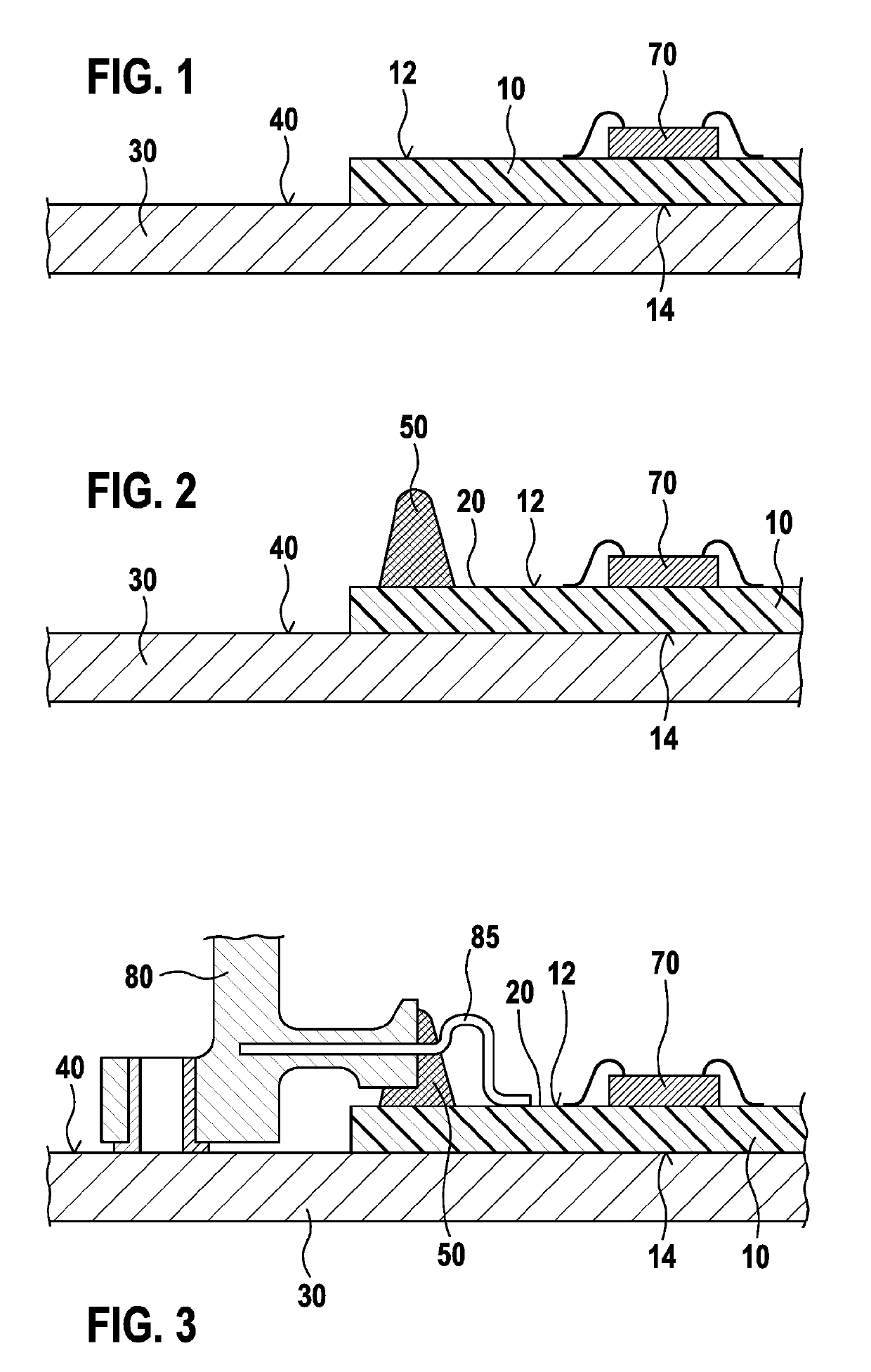
[0026]FIG. 1 shows a schematic view after a first step of the method according to the invention for producing an electronic assembly 5. The electronic assembly 5 may be part of a transmission control module for a vehicle.

[0027]First, a printed circuit board 10 (PCB) is provided. The printed circuit board 10 has a first side 12 (on top in FIG. 1) and a second side 14 (underneath in FIG. 1), the second side 14 being opposite from the first side 12. Arranged on the first side 12 of the printed circuit board 10 is at least one first electronic component 70. The first electronic component 70 is electrically connected to the printed circuit board 10.

[0028]The printed circuit board 10 is arranged on a reference surface 40. The second side 14 of the printed circuit board is connected over its surface area to the reference surface 40 or is fastened on it. Alternatively, it may also be only during production that the printed circuit board lies on a reference surface or mounting surface or a s...


PUM


Abstract

A method for producing an electronic assembly includes providing a printed circuit board with a first face, a second face facing away from the first face, and a first component arranged on the first face. The method further includes arranging the circuit board such that the second face lies on a reference surface, and applying a sealing material which is substantially not flowable prior to being cured onto the first face. The sealing material surrounds a sub-region of the first face of the circuit board. The method further includes arranging a second component at least partly on the reference surface such that the second component is pressed into the sealing material, electrically connecting the second component to the circuit board via an electric connection line, and applying a covering material onto the circuit board first face sub-region surrounded by the sealing material and onto the first component.

Description

FIELD OF THE INVENTION[0001]The invention relates to a method for producing an electronic assembly and to an electronic assembly, in particular for a transmission control module.PRIOR ART[0002]Many electronic assemblies are known. If it is for example part of a transmission control module, the electronic assembly must be sealed in an oil-proof manner, since the transmission control module is surrounded by oil. The electronic assembly usually comprises a printed circuit board with electronic components arranged on it.[0003]Large individual components, such as for example sensors, are to some extent not arranged on the printed circuit board and are electrically connected to the printed circuit board. Since the oil often contains conductive particles, an electrical insulation of the components and of the electrical connection between the large individual component that is not arranged (completely) on the printed circuit board and the printed circuit board is necessary. Generally used f...

Claims


Application Information

Patent Timeline
IPC IPC(8): H05K5/00H05K3/28H05K5/06H05K1/02H05K1/18
CPCH05K5/0082H05K3/284H05K5/065H05K1/0203H05K1/181H05K2201/09909H05K2201/1031H05K2201/10151H05K2203/1316H05K2203/1327H05K2201/066H05K2203/167Y02P70/50H01L2224/48091H01L2924/181H01L2224/48227H01L2924/00014H01L2924/00012
Inventor ZWEIGLE, PETERDERINGER, HELMUTHOFFMANN, JENS
Owner ROBERT BOSCH GMBH
Why Eureka
Try Eureka