Choke coil
- Summary
- Abstract
- Description
- Claims
- Application Information
AI Technical Summary
Benefits of technology
Problems solved by technology
Method used
Image
Examples
first embodiment
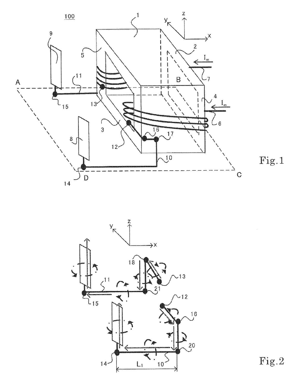
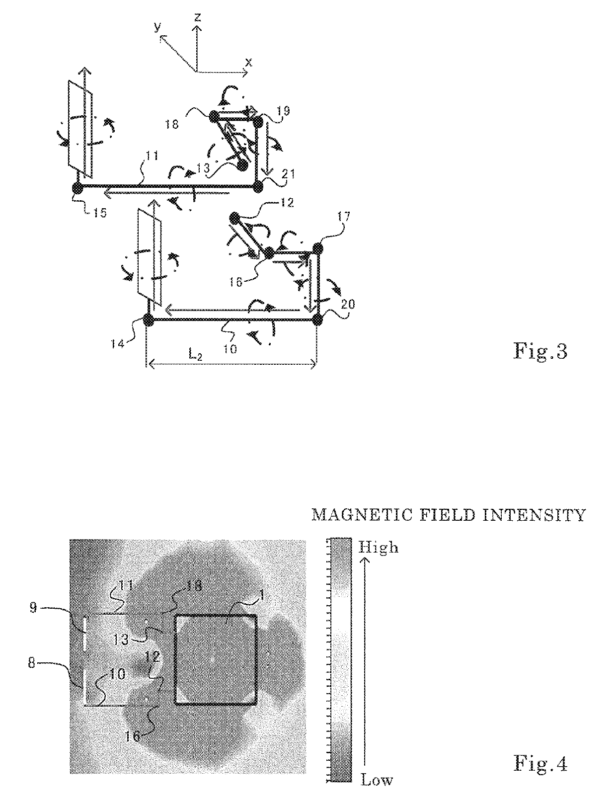
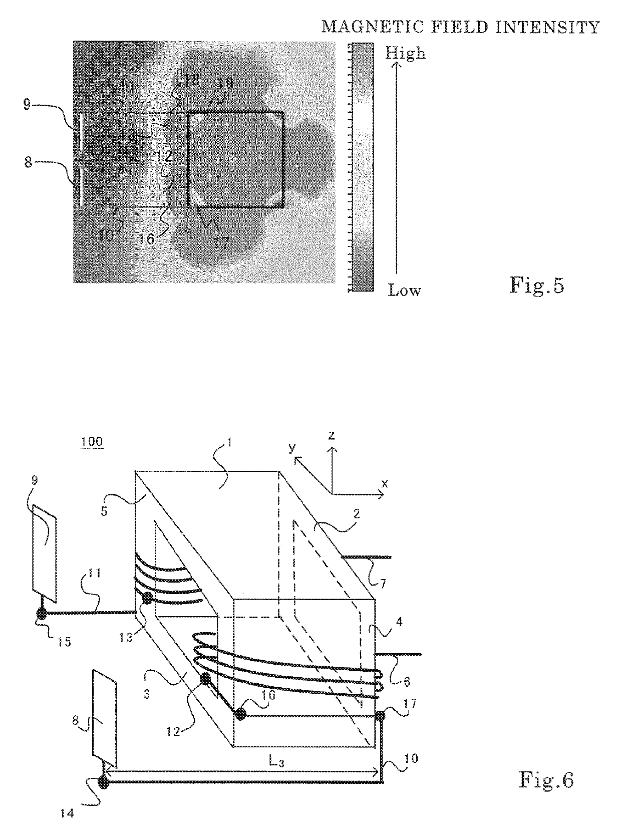
[0026]FIG. 1 is a perspective view for illustrating a choke coil according to a first embodiment of the present invention. In FIG. 1, a choke coil 100 includes an upper yoke 2, a lower yoke 3, a first pier column 4, and a second pier column 5, which make up a magnetic body 1; a positive winding wire 6 and a negative winding wire 7, which are wound around the first pier column 4 and the second pier column 4, respectively; and a positive connector connection line 10, which electrically connects the positive winding wire 6 and a connector positive conductor 8, and a negative connector connection line 11, which electrically connects the negative winding wire 7 and a connector negative conductor 9.
[0027]The upper yoke 2 and the lower yoke 3 are arranged side by side along a z-axis direction. The first pier column 4 and the second pier column 5 are arranged side by side along a y-axis direction. The upper yoke 2, the lower yoke 3, the first pier column 4, and the second pier column 5 are ...
second embodiment
[0055]FIG. 7 is a perspective view for illustrating a choke coil according to a second embodiment of the present invention. The configuration of a coil main body in the second embodiment is the same as that in the first embodiment described above, and a description on the configuration of the coil main body is therefore omitted.
[0056]In FIG. 7, the positive winding wire 6 is connected to a positive flat connection line 28 at the positive winding wire bending point 12. The negative winding wire 7 is connected, though not shown, to a negative flat connection line at the negative winding wire bending point 13. The positive flat connection line 28 is led out from the positive winding wire bending point 12 along the y-axis direction, and is bent to the z-axis direction at the positive yx inflection point 16. The positive flat connection line 28 bent to the z-axis direction is connected to a positive flat board 22 at the positive zx inflection point 20.
[0057]Though not shown, the negative...
third embodiment
[0070]FIG. 9 is a perspective view for illustrating a choke coil according to a third embodiment of the present invention. The choke coil 100 of FIG. 9 is obtained by providing a normal mode capacitor 29 between the positive flat board 22 and the negative flat board 23 in the choke coil 100 illustrated in FIG. 7. The rest of the configuration of the third embodiment is the same as that in the second embodiment described above, and hence a description on the rest of the configuration is omitted.
[0071]Effects of the choke coil 100 configured as above are now described. In FIG. 9, the normal mode capacitor 29 is provided between the positive flat board 22 and the negative flat board 23 in order to bypass a noise current In, which flows in the positive winding wire 6, when the noise current In and a noise current −In, which flows in the negative winding wire 7, are in directions opposite from each other.
[0072]In this case, the inductance of a portion from the positive zx inflection poin...
PUM
 Abstract
Description
Claims
Application Information
 - R&D
- Intellectual Property
- Life Sciences
- Materials
- Tech Scout
- Unparalleled Data Quality
- Higher Quality Content
- 60% Fewer Hallucinations
Browse by: Latest US Patents, China's latest patents, Technical Efficacy Thesaurus, Application Domain, Technology Topic, Popular Technical Reports.
© 2025 PatSnap. All rights reserved.Legal|Privacy policy|Modern Slavery Act Transparency Statement|Sitemap|About US| Contact US: help@patsnap.com


