
Rear muffler of sedan

A technology for mufflers and cars, applied in the direction of mufflers, machines/engines, gas passages, etc., it can solve the problems of reducing the volume of two chambers, which will affect the noise reduction effect of the muffler, and large noise, so as to reduce noise and increase volume , Improve the effect of noise reduction effect

Pending Publication Date: 2018-09-11
成英
View PDF0 Cites 0 Cited by
  • Summary
  • Abstract
  • Description
  • Claims
  • Application Information

AI Technical Summary

Problems solved by technology

The rear muffler on a car has an intake pipe, a cylinder and an exhaust pipe arranged in sequence from front to back. The cylinder of the rear muffler is generally composed of two chambers at the front and rear, and the front end of the cylinder is gradually smaller from the back to the front. Conical surface, the rear end surface of the cylinder is a tapered surface that gradually decreases from front to back, so that the front and rear ends of the cylinder are compressed, reducing the volume of the two chambers, which will affect the noise reduction effect of the muffler
At the same time, the existing muffler does not have a structure that completely eliminates noise for the 80HZ wave frequency band, and the wave frequency band around 80HZ is just the main concentration point of the car's noise, so the car still has a lot of noise after the noise reduction by the muffler

Method used


Image

  • Rear muffler of sedan
  • Rear muffler of sedan

Examples


Embodiment Construction

[0016] Below in conjunction with accompanying drawing and embodiment the present invention will be further described:

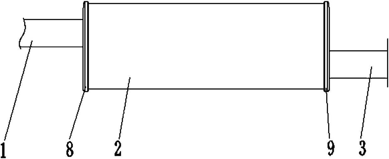
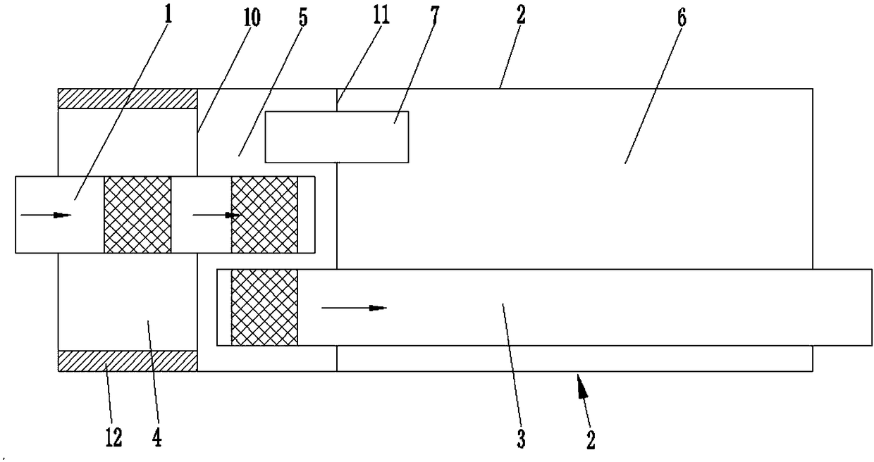
[0017] like figure 1 and figure 2 Shown, the present invention is made up of intake pipe 1, cylinder body 2, exhaust pipe 3, first chamber 4, second chamber 5, third chamber 6, through pipe 7, front cover 8, back cover 9, front The partition board 10 and the rear partition board 11 etc. are composed. Wherein, the cylindrical body 2 is a circular straight cylindrical structure, the front end of the cylindrical body 2 is sealed by a front cover 8, and the rear end is sealed by a rear cover 9. Both the front cover 8 and the rear cover 9 are preferably circular flat plates, and are welded and Body 2 is fixed. The inside of the cylinder 2 is divided into three chambers by the front partition 10 and the rear partition 11, from front to back are the first chamber 4, the second chamber 5 and the third chamber 6, the first chamber 4 The volume of the second chamb...


PUM

PropertyMeasurementUnit
Lengthaaaaaaaaaa
Lengthaaaaaaaaaa
Diameteraaaaaaaaaa

Abstract

The invention discloses a rear muffler of a sedan. The interior of a cylindrical shell is divided into three cavities by a front separation plate and a back separation plate. The three cavities are orderly a first cavity, a second cavity and a third cavity from front to back. A circle of muffling material is arranged on the inner ring wall of the first cavity. The back end of an air inlet pipe penetrates through a front cover and the front separation plate from front to back and stretches into the second cavity. A pipe body, located on the first cavity and the second cavity, of the air inlet pipe is equipped with circulation meshes. The front end of an exhaust pipe penetrates through a back cover and a back separation plate from back to front and stretches into the second cavity. A pipe body, located on the second cavity, of the exhaust pipe is equipped with a circulation mesh. The upper part of the back separation plate is provided with a communicating pipe in a penetrating manner. Byarranging the communicating pipe in a penetrating manner on the back separation plate, sound waves are eliminated by adoption of the principle that friction interference of sound waves in the same frequency is eliminated. Meanwhile, the flat-plate-shaped front cover and the back cover are adopted in order to increase the volume of the silencer. Therefore, the muffling effect of the muffler is greatly improved.

Description

technical field [0001] The invention relates to a muffler, in particular to a rear muffler on a car. Background technique [0002] Automobile mufflers are commonly used components of automobiles, which are conducive to reducing noise pollution during driving. The rear muffler on a car has an intake pipe, a cylinder and an exhaust pipe arranged in sequence from front to back. The cylinder of the rear muffler is generally composed of two chambers at the front and rear, and the front end of the cylinder is gradually smaller from the back to the front. Conical surface, the rear end surface of the cylinder is a tapered surface that gradually decreases from front to back, so that the front and rear ends of the cylinder are compressed, reducing the volume of the two chambers, which will affect the noise reduction effect of the muffler. At the same time, the existing muffler does not have a structure that completely eliminates noise for the 80HZ wave frequency band, and the wave fr...

Claims


Application Information

Patent Timeline
IPC IPC(8): F01N1/06F01N1/08F01N1/10F01N13/00
CPCF01N1/06F01N1/082F01N1/10F01N13/007F01N2210/06F01N2470/02F01N2470/20
Inventor 刘博文
Owner 成英
Learn More