Combustor Assembly for a Turbine Engine

a turbine engine and compressor technology, applied in the direction of engine starters, machines/engines, lighting and heating apparatus, etc., can solve the problems of affecting the durability of liners, affecting the efficiency of liners, and causing bending stress and strain on liners

Inactive Publication Date: 2019-07-04
GENERAL ELECTRIC CO
View PDF0 Cites 3 Cited by
  • Summary
  • Abstract
  • Description
  • Claims
  • Application Information

AI Technical Summary

Problems solved by technology

As the combustion gases flow downstream through the combustion chamber, the combustion gases scrub along the liners, causing the liners to rapidly heat up.
However, the forward ends of the liners, or the portions of the liners that attach with dome sections, typically do not heat up as quickly as the rest of their respective liners.
The thermal lag at the forward ends of the liners may cause undesirable bending stress and strain on the liners.
As gas turbine engines may undergo many rapid power increases over many engine cycles, such repeated stress and strain on the liners can negatively impact their durability.

Method used


Image

  • Combustor Assembly for a Turbine Engine
  • Combustor Assembly for a Turbine Engine
  • Combustor Assembly for a Turbine Engine

Examples


Embodiment Construction

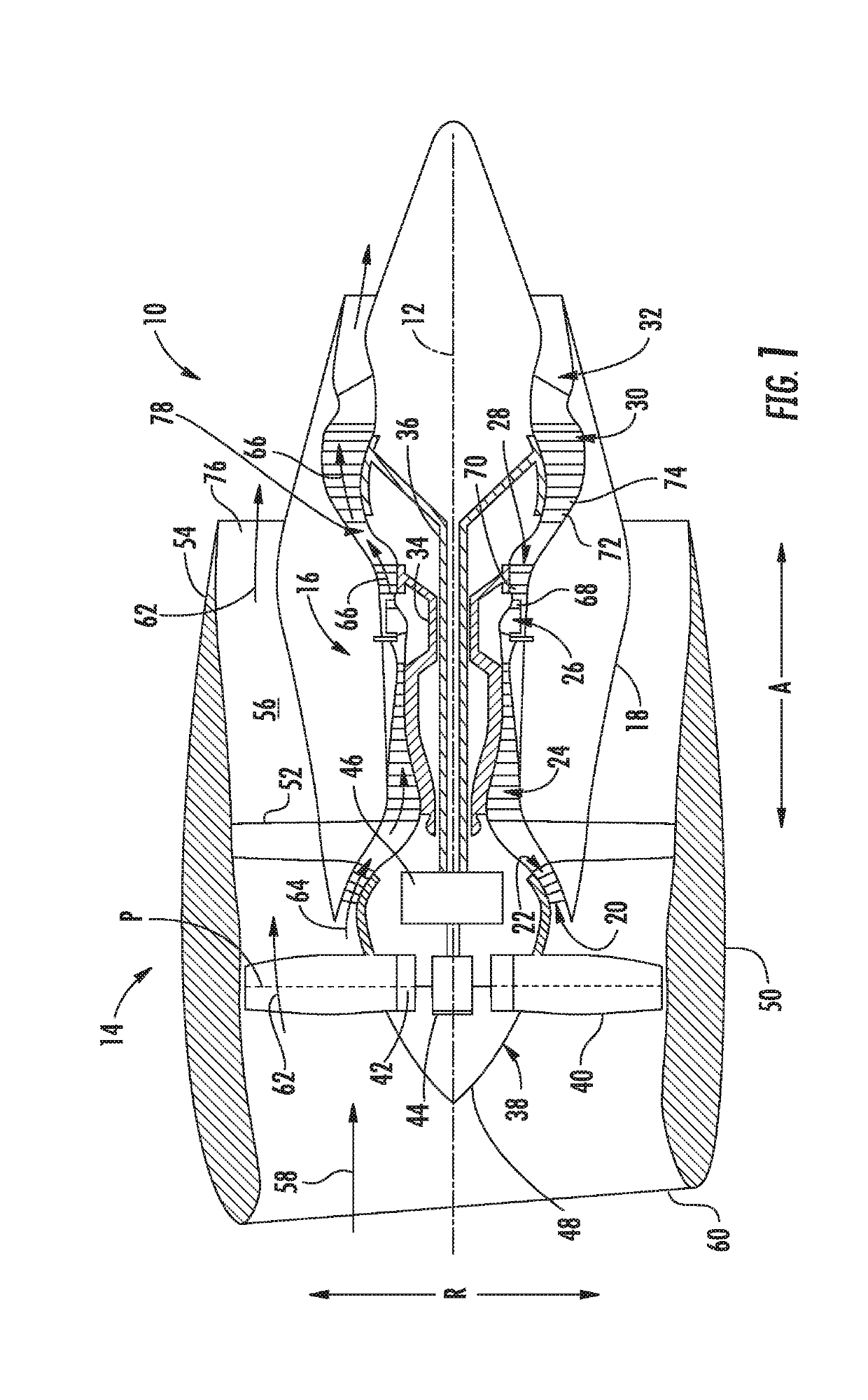
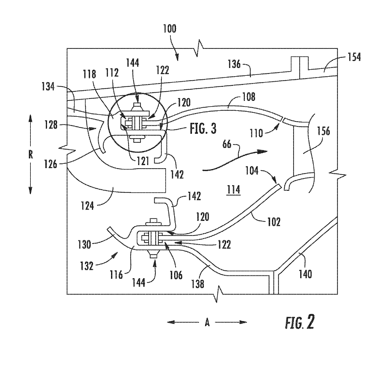
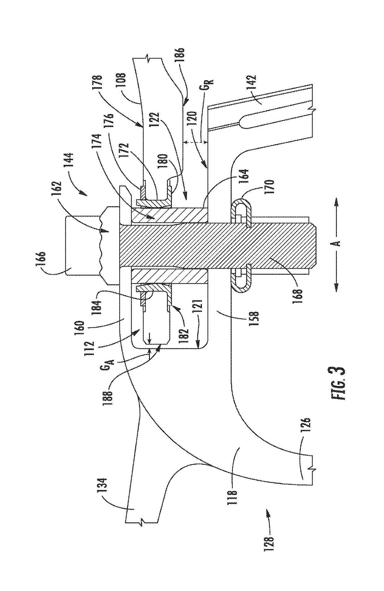
[0019]Reference will now be made in detail to present embodiments of the invention, one or more examples of which are illustrated in the accompanying drawings. The detailed description uses numerical and letter designations to refer to features in the drawings. Like or similar designations in the drawings and description have been used to refer to like or similar parts of the invention. As used herein, the terms “first”, “second”, and “third” may be used interchangeably to distinguish one component from another and are not intended to signify location or importance of the individual components. The terms “forward” and “aft” refer to relative positions within a gas turbine engine, with forward referring to a position closer to an engine inlet and aft referring to a position closer to an engine nozzle or exhaust. The terms “upstream” and “downstream” refer to the relative direction with respect to fluid flow in a fluid pathway. For example, “upstream” refers to the direction from whic...


PUM


Abstract

A combustor assembly for a gas turbine engine includes a dome defining a slot. The combustor assembly also includes a liner at least partially defining a combustion chamber and extending between an aft end and a forward end. At least a portion of the forward end is received within the slot of the dome. The forward end of the liner defines a plurality of warming holes that allow for a warming airflow to flow therethrough to warm the forward end at a faster rate during transient operating conditions of the engine thereby reducing transient stresses and increasing liner durability.

Description

FEDERALLY SPONSORED RESEARCH[0001]This invention was made with government support under contact number FA8626-16-C-2138 awarded by the Department of the Air Force. The U.S. government may have certain rights in the invention.FIELD[0002]The present subject matter relates generally to gas turbine engines, and more particularly to combustor assemblies for gas turbine engines.BACKGROUND[0003]A gas turbine engine generally includes a fan and a core arranged in flow communication with one another. Additionally, the core of the gas turbine engine general includes, in serial flow order, a compressor section, a combustion section, a turbine section, and an exhaust section. In operation, air is provided from the fan to an inlet of the compressor section where one or more axial compressors progressively compress the air until it reaches the combustion section. Fuel is mixed with the compressed air and burned within the combustion section to provide combustion gases. The combustion gases are ro...

Claims


Application Information

Patent Timeline
Patent Type & Authority Applications(United States)
IPC IPC(8): F01D25/10F01D19/02F02C9/18F23R3/00F23R3/04
CPCF01D25/10F01D19/02F02C9/18F23R3/002F23R3/007F23R3/04F05D2220/323F05D2300/6033F05D2240/35F05D2260/941F23R3/06F23R3/60F23R2900/00005F23R2900/03042F02C3/14Y02T50/60
Inventor STIEG, MICHAEL ALANBLOOM, NICHOLAS JOHNNEWBURN, ERIC RYANGEISER, BRETT JOSEPH
Owner GENERAL ELECTRIC CO
Why Eureka
Try Eureka