Wind turbine blade for a wind turbine
- Summary
- Abstract
- Description
- Claims
- Application Information
AI Technical Summary
Benefits of technology
Problems solved by technology
Method used
Image
Examples
Embodiment Construction
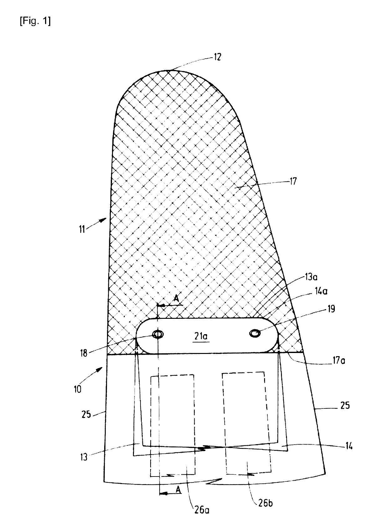
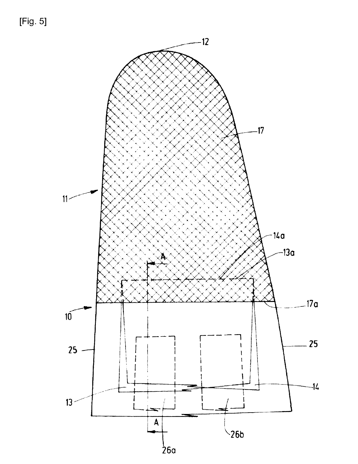
[0065]FIG. 1 shows a top view of a section of a wind turbine blade 10 comprising a tip end area 11 and a tip end 12, wherein the tip end 12 is disposed in the tip end area 11. The wind turbine blade 10 further has a lightning protection system comprising two metal foils 13, 14 formed as strips out of copper which both have a first end 13a, 14a disposed in the tip end area 11 of the blade 10. The metal foils 13, 14 extend from their first ends 13a, 14a along the longitudinal direction of the blade 10 towards its root end.
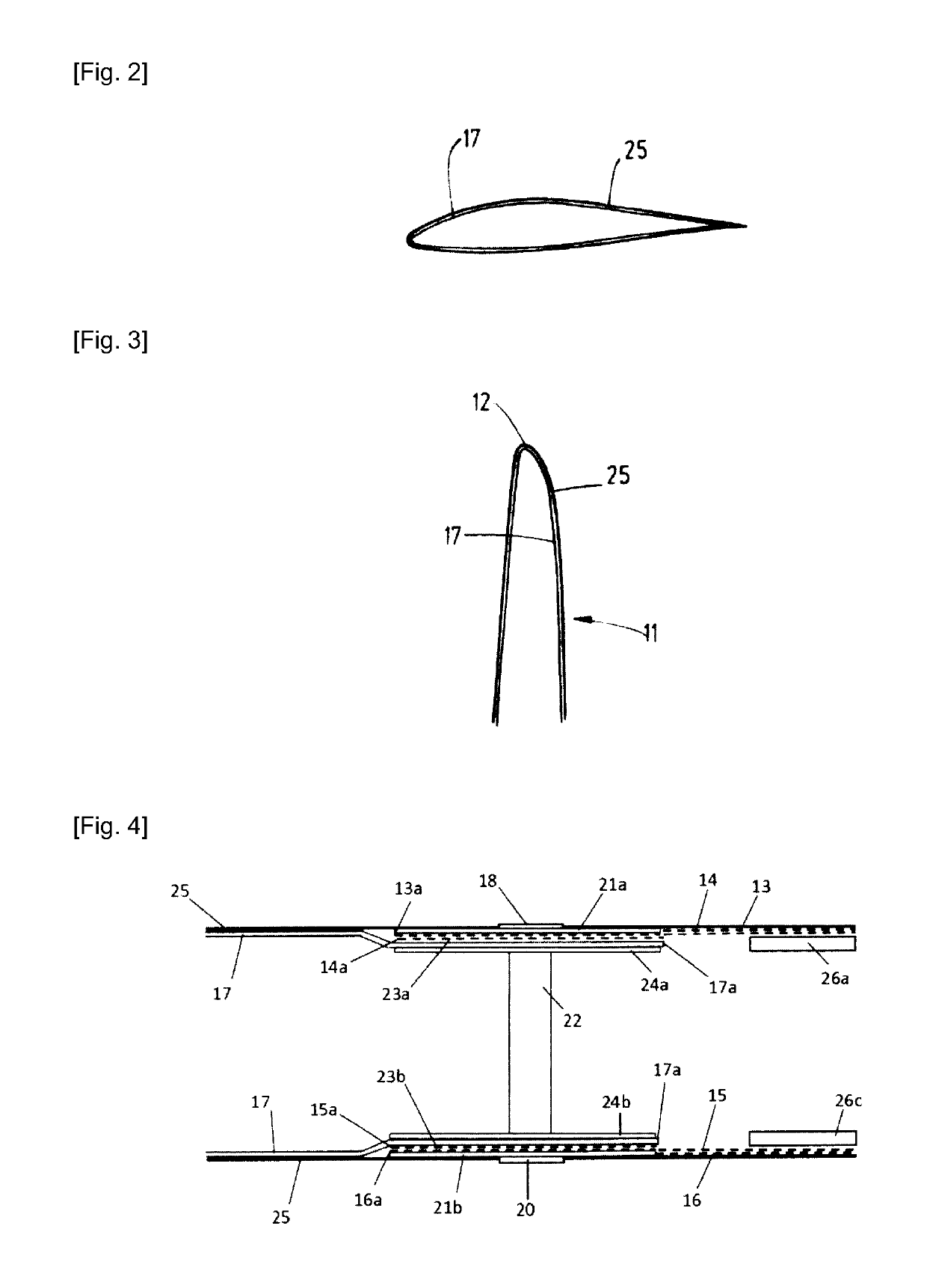
[0066]The blade 10 further comprises an outer blade layer 25 (see FIGS. 2 and 3) of which in FIG. 1 only the outline is shown. The metal foils 13, 14 are arranged in radial direction behind spar caps 26a, 26b which are located underneath the outer blade layer 25. Since the spar caps 26a, 26b are disposed underneath the outer blade layer and the metal foils 13, 14, the spar caps 26a, 26b are shown by broken lines. The spar caps 26a, 26b extend from the root end of the...
PUM
 Abstract
Description
Claims
Application Information
 - R&D
- Intellectual Property
- Life Sciences
- Materials
- Tech Scout
- Unparalleled Data Quality
- Higher Quality Content
- 60% Fewer Hallucinations
Browse by: Latest US Patents, China's latest patents, Technical Efficacy Thesaurus, Application Domain, Technology Topic, Popular Technical Reports.
© 2025 PatSnap. All rights reserved.Legal|Privacy policy|Modern Slavery Act Transparency Statement|Sitemap|About US| Contact US: help@patsnap.com


