
Building automation system

a technology for building automation and building automation, applied in the field of building automation systems, can solve the problems of inability to implement a further function, the server-client structure of these systems, and the inability to manage confidential data on the instance or central server

Active Publication Date: 2019-06-20
INNOGY INNOVATION GMBH
View PDF8 Cites 4 Cited by
  • Summary
  • Abstract
  • Description
  • Claims
  • Application Information

AI Technical Summary

Benefits of technology

The patent text describes a new building automation system that uses a peer-to-peer network to manage and control the system, instead of a central server or platform. This is achieved through a controlling means that provides a second function module to appliance devices, allowing for easy customization and high security standards. The use of a peer-to-peer network reduces transaction costs and simplifies system management. The network can be formed by a plurality of computer nodes and a peer-to-peer module. Overall, the technology provides greater flexibility, security, and efficiency for managing and controlling building automation systems.

Problems solved by technology

Further, according to prior art it is generally not possible to implement a further function into an appliance device after the manufacturing process.
A further disadvantage of such building automation systems is the server-client structure of these systems.
A disadvantage of server-client structures of this kind, particularly the server (or platform), apart from the high transaction costs, is that the central instance or central server manages confidential data, such as user data including e.g. access data for accessing the appliance devices.
A persistent problem affecting the central instance is that of protecting the confidential data stored on one or more server(s) from access by unauthorized third parties.
In particular, a high degree of security expenditure is required, in order to prevent said data from being tampered with.
This in turn leads to higher transaction costs.
A further disadvantage is the complex and costly infrastructure for providing the described server-client structure.
Furthermore, it is not possible to update a first function module a simple and secure manner.

Method used


Image

  • Building automation system
  • Building automation system
  • Building automation system

Examples


Embodiment Construction

[0110]Like reference numerals in different figures indicate like elements.

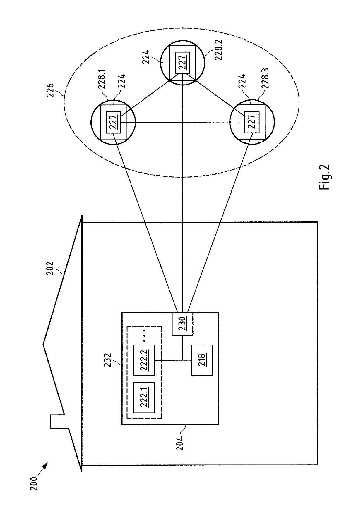
[0111]FIG. 2 shows a schematic view of an embodiment of a building automation system 200 according to the present invention. The building automation system 200 comprises a building entity 202 in form of a building 202. In the present example, the building automation system 200 comprises only one appliance device 204. It shall be understood that a building automation system may comprise a plurality of appliance devices.

[0112]The depicted appliance device 204 comprises an actor218. It shall be understood that an appliance device can comprise two or more actors and / or one or more sensors. In the present example, the actor 218 is connected with a rewritable storage unit 232. The storage unit 232 is configured such that function modules 222.1, 222.2 can be stored, changed and / or deleted after the manufacturing of the appliance device 204.

[0113]The rewritable storage unit 232 comprises a first function module 222.1 ...


PUM


Abstract

Disclosed herein are embodiments of a building automation system. The building automation system includes at least one first appliance device having an actor and / or a sensor. The first appliance device includes a first function module and is configured to operate in accordance with the first function module in order to provide a first function. The building automation system also includes a peer-to-peer network with a peer-to-peer application and a peer-to-peer module assigned to the first appliance device and configured to communicate with the peer-to-peer application. The peer-to-peer application includes a controlling means configured to provide a second function module to the first appliance device by means of the peer-to-peer module assigned to the first appliance device, and the first appliance device is configured to operate in accordance with the second function module in order to provide at least one second function.

Description

CROSS-REFERENCE TO RELATED PATENT APPLICATION[0001]This patent application is a continuation of PCT / EP2016 / 068950, filed Aug. 9, 2016, the entire teachings and disclosure of which are incorporated herein by reference thereto.FIELD[0002]The invention relates to a building automation system comprising at least one first appliance device comprising at least one actor and / or at least one sensor, wherein the first appliance device comprises at least one first function module, wherein the first appliance device is configured to operate in accordance with the first function module in order to provide at least one first function. The invention also relates to a method for operating a building automation system, an appliance device and a peer-to-peer application.BACKGROUND[0003]Communication systems with one or more sensor(s) and / or one or more actor(s) are known from prior art. An example of such a communication system is a building automation system. A building automation system according ...

Claims


Application Information

Patent Timeline
Patent Type & Authority Applications(United States)
IPC IPC(8): H04L12/28H04L12/12
CPCH04L12/2816H04L12/12H04L12/2807G05B15/02G05B2219/2613
Inventor REINELT, JENSSTOCKER, CARSTENWAFFNER, JURGEN
Owner INNOGY INNOVATION GMBH
Learn More