
Nasal interface apparatus and systems for use with a respiratory assist device

a technology of nasal interface and respiratory assist device, which is applied in the direction of respiratory devices, medical devices, other medical devices, etc., can solve the problems of not facilitating the mobility or activities of the patient's daily life, and the known non-invasive face or nasal mask is bulky and cumbersome. , to achieve the effect of increasing the net volume of airway pressure, reducing the burden on the patient, and reducing the burden

Active Publication Date: 2019-06-13
INOGEN INC
View PDF0 Cites 4 Cited by
  • Summary
  • Abstract
  • Description
  • Claims
  • Application Information

AI Technical Summary

Benefits of technology

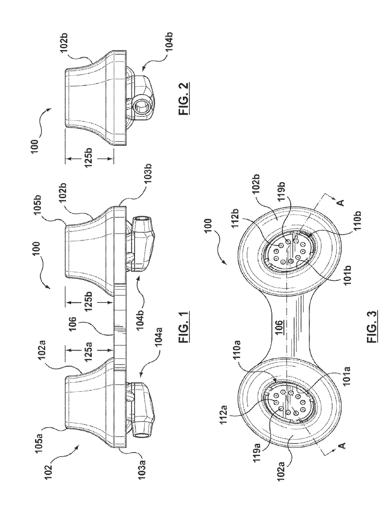
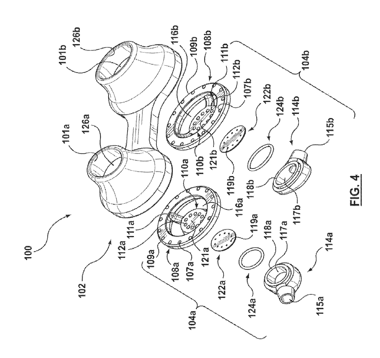
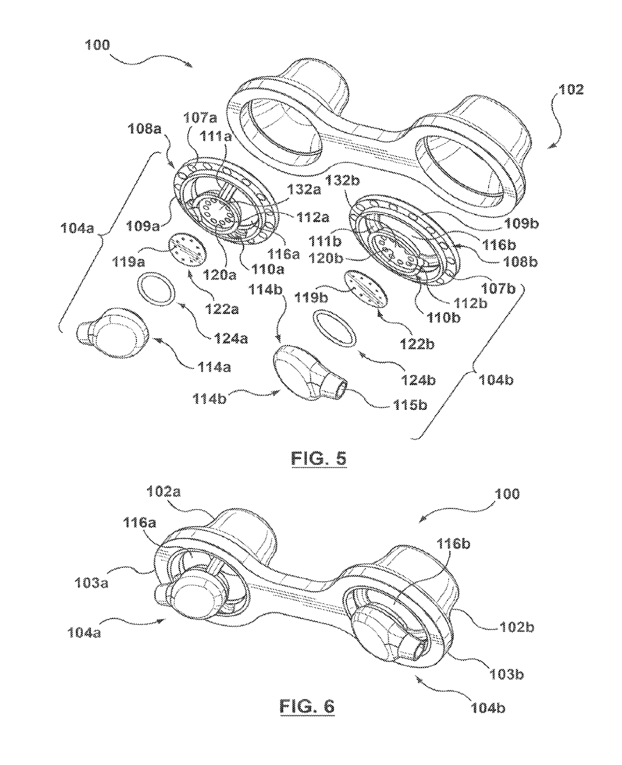
[0010]An ambulatory assist ventilation (AAV) apparatus and system are disclosed for the delivery of a respiratory gas to assist the spontaneous breathing effort of a patient with a breathing disorder. The AAV system includes a compressed respiratory gas source, a respiratory assist device for controlling respiratory gas flow, and a low profile open nasal interface device, which does not have a dead space or hollow area where CO.sub.2 can collect, and patient circuit tubing for delivering the respiratory gas to the patient, wherein the nasal interface device is fluidly connected to the respiratory assist device via tubing for receiving the respiratory gas therefrom. The nasal interface device operates under the Venturi principle by utilizing the energy of the delivered respiratory gas to entrain ambient air and increase airway pressure thereby increasing the net volume delivered to the patient. Embodiments of nasal interface device disclosed herein are configured in an open, compact, low profile manner, which does not have a dead space or hollow area where CO.sub.2 can collect, and are significantly smaller, lighter in weight and higher performing as compared to known breathing masks.

Problems solved by technology

While helpful in supporting the work of breathing, the patient interfaces used for invasive MV are obtrusive and / or invasive to the user, and obviously would not facilitate mobility or activities of daily living of the patient.
However, known non-invasive face or nasal masks are bulky and cumbersome and require a patient circuit with large diameter tubing that restricts movement and is also bulky and cumbersome.
The bulky nature of known masks and patient circuits create a ‘dead space’ in the hollow areas of the mask and patient circuit.
This dead space, coupled with the requirement of a closed system result in carbon dioxide (CO.sub.2) accumulating in the ‘dead space’ or hollow areas of the mask and patient circuit.
Also, closed circuit ventilation systems increase the risk of the ventilator over pressurizing the patient's lungs, which can result in trauma to the airway tissues and then longer-term patient ventilator dependency.
Consequently, known invasive and non-invasive mechanical ventilation systems do not facilitate activities of daily living of the patient or mobility and present risks of trauma to the patient's breathing tissues.
While effective, this therapy has poor patient compliance because the patient interface and corresponding patient circuit tubing is obtrusive to the patient.
As with mechanical invasive and non-invasive ventilation, the bulky nature of the CPAP and BiPAP masks and patient circuits create a ‘dead space’ in the hollow areas of the mask and patient circuit.
This dead space, coupled with the requirement of a closed system result in CO.sub.2 accumulating in the ‘dead space’ or hollow areas of the mask and patient circuit.
Also, the closed circuit ventilation systems, such as CPAP and BiPAP, require the patient, in most instances, to unnaturally breathe through both a mask and gas delivery circuit, which can be uncomfortable.
While oxygen therapy has been demonstrated to improve lifespan, there is a lack of evidence demonstrating that oxygen therapy can reduce the severe feelings of breathlessness, work of breathing and discomfort a patient experiences resulting from the above noted syndromes.
Thus when worn by the patient, the overall size and weight of the nasal interface and patient circuit tubing associated therewith is not insubstantial and may even be considered by some patients as cumbersome and / or burdensome.

Method used


Image

  • Nasal interface apparatus and systems for use with a respiratory assist device
  • Nasal interface apparatus and systems for use with a respiratory assist device
  • Nasal interface apparatus and systems for use with a respiratory assist device

Examples


Embodiment Construction

[0043]Specific embodiments of the present invention are now described with reference to the figures, wherein like reference numbers indicate identical or functionally similar elements. The terms “proximal” and “distal” are used in the following description with respect to a position or direction relative to the respiratory assist device. “Proximal” and “proximally” are a position near from or in a direction toward the respiratory assist device. “Distal” or “distally” are a position distant or in a direction away from the respiratory assist device.

[0044]The following detailed description is merely exemplary in nature and is not intended to limit the invention or the application and uses of the invention. Although the descriptions of embodiments hereof are in the context of treatment of a range of clinical syndromes that require respiratory assistance, the invention may also be used in any other therapies and / or situations where it is deemed useful. Furthermore, there is no intention ...


PUM


Abstract

An ambulatory assist ventilation (AA V) apparatus and system are disclosed for the delivery of a respiratory gas to assist the spontaneous breathing effort of a patient with a breathing disorder. The AA V system includes a compressed respiratory gas source, a respiratory assist device for controlling respiratory gas flow to the patient, a patient circuit tubing and a low profile nasal interface device, which does not have a dead space or hollow area where C02 can collect, for delivering the respiratory gas to the patient, wherein the nasal interface device is fluidly connected to the respiratory assist device via tubing for receiving the respiratory gas therefrom.

Description

CROSS-REFERENCE TO RELATED APPLICATION[0001]This application is a continuation of the co-pending U.S. patent application titled, “NASAL INTERFACE APPARATUS AND SYSTEMS FOR USE WITH A RESPIRATORY ASSIST DEVICE,” filed on Mar. 12, 2015 and having Ser. No. 14 / 427,986, which is a national phase application of the international application titled, “NASAL INTERFACE APPARATUS AND SYSTEMS FOR USE WITH A RESPIRATORY ASSIST DEVICE,” filed Aug. 27, 2013 and having Serial No. PCT / US2013 / 056702, which claims the priority benefit of the U.S. Provisional Patent application having Ser. No. 61 / 699,969, filed Sep. 12, 2012. The subject matter of these related applications is hereby incorporated herein by reference.FIELD OF THE INVENTION[0002]The invention is directed to the delivery of a respiratory gas to assist the spontaneous breathing effort of a patient with a breathing disorder, and more particularly to ambulatory nasal interface apparatus and systems for delivering the respiratory gas to the p...

Claims


Application Information

Patent Timeline
Patent Type & Authority Applications(United States)
IPC IPC(8): A61M16/06A61M16/00A61M16/20
CPCA61M16/0666A61M16/0003A61M16/0063A61M16/0622A61M16/201A61M16/0605A61M16/0677A61M16/204A61M16/022A61M2210/0618A61M16/0833A61M2016/0021A61M2202/0208A61M2205/3331A61M2016/0027A61M16/0866A61M16/127A61M2202/0007
Inventor ALLUM, TODD W.KAPUST, GREGORY J.
Owner INOGEN INC
Learn More