
System and method for ablating a tissue site by electroporation with real-time monitoring of treatment progress

a tissue site and control system technology, applied in computer-aided planning/modelling, surgery, enzymology, etc., can solve the problems of inability to monitor the progress of the treatment procedure, inability to monitor the specifics of the actual case, and inability to alter the settings, so as to improve the likelihood of successful treatment and improve the treatment delivery

Inactive Publication Date: 2019-06-13
VIRGINIA TECH INTPROP INC +1
View PDF0 Cites 36 Cited by
  • Summary
  • Abstract
  • Description
  • Claims
  • Application Information

AI Technical Summary

Benefits of technology

This approach enables improved treatment delivery and increased success rates by providing real-time feedback on tissue electroporation progress and endpoint determination, ensuring clinically sufficient ablation of targeted regions.

Problems solved by technology

As can be appreciated, the electroporation therapy treatment plans selected by the physician are limited to using a retrospective dimension data approach, where a pre-determined pulse parameter protocol is delivered between each electrode pair in an array and the pulse parameters are selected from previously existing ablation data.
However, this approach ignores the specifics of the actual case, which will vary both in terms of initial tissue properties and tissue response to the electroporation pulses for each patient.
Specifically, there is no way to monitor the progress of the treatment procedure or alter the settings other than to stop the procedure manually.
Thus, even when the procedure completes normally, there was no assurance that there were clinically sufficient electroporation of the targeted region due to the unpredictable nature of patient environments and living tissue.

Method used


Image

  • System and method for ablating a tissue site by electroporation with real-time monitoring of treatment progress
  • System and method for ablating a tissue site by electroporation with real-time monitoring of treatment progress
  • System and method for ablating a tissue site by electroporation with real-time monitoring of treatment progress

Examples


Embodiment Construction

[0019]Throughout the present teachings, any and all of the one, two, or more features and / or components disclosed or suggested herein, explicitly or implicitly, may be practiced and / or implemented in any combinations of two, three, or more thereof, whenever and wherever appropriate as understood by one of ordinary skill in the art. The various features and / or components disclosed herein are all illustrative for the underlying concepts, and thus are non-limiting to their actual descriptions. Any means for achieving substantially the same functions are considered as foreseeable alternatives and equivalents, and are thus fully described in writing and fully enabled. The various examples, illustrations, and embodiments described herein are by no means, in any degree or extent, limiting the broadest scopes of the claimed inventions presented herein or in any future applications claiming priority to the instant application.

[0020]In the present specification, the voltage value of any AC si...


PUM


Abstract

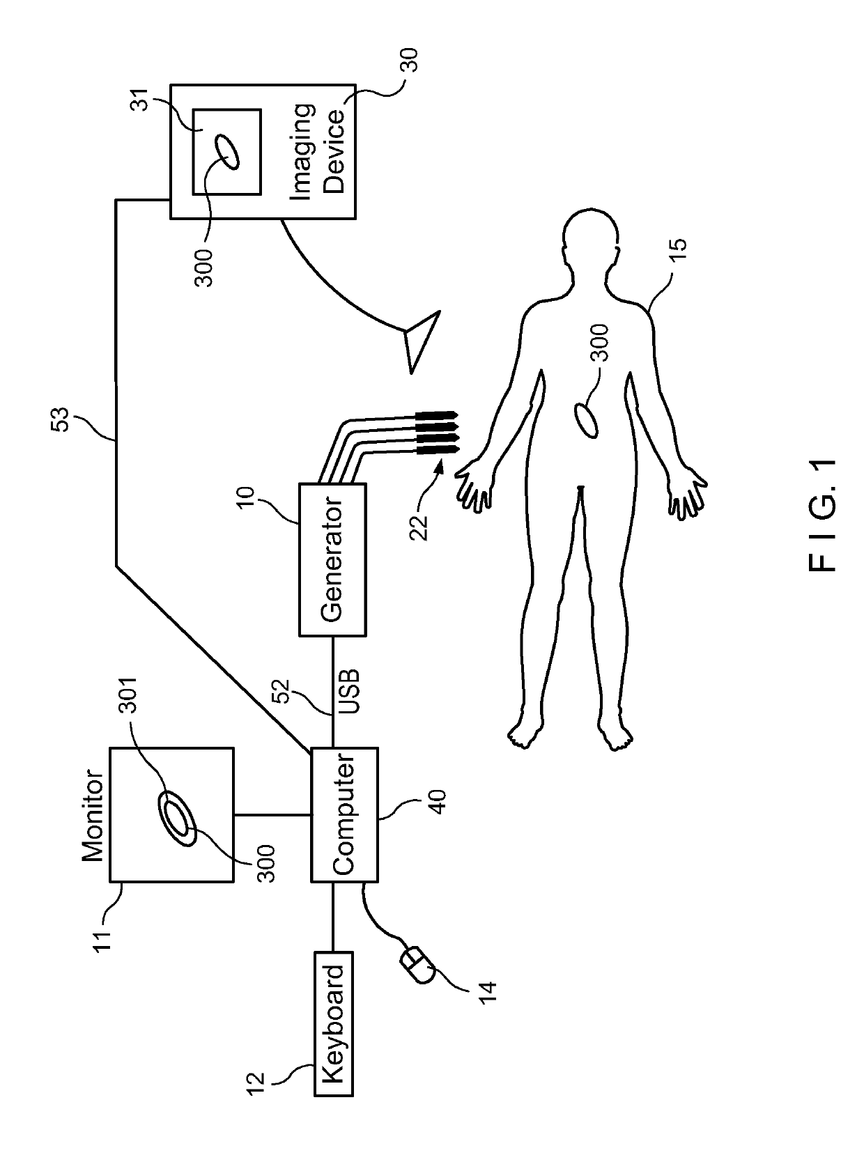
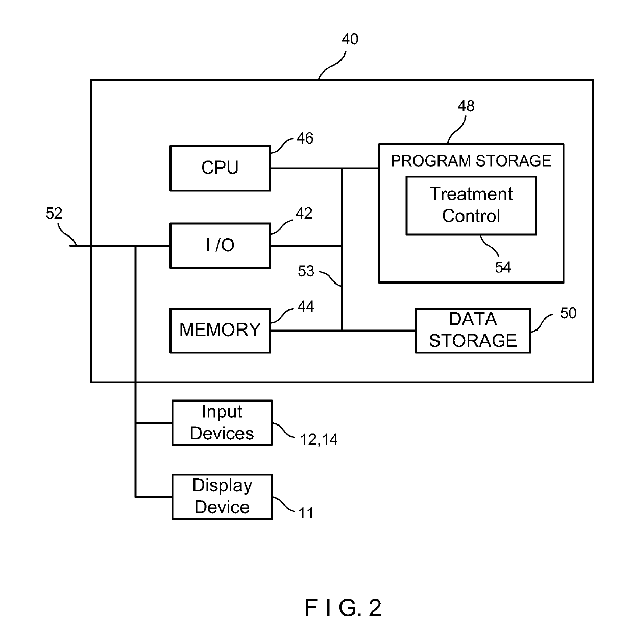
A medical system for ablating a tissue site with real-time monitoring during an electroporation treatment procedure. A pulse generator generates a pre-treatment (PT) test signal prior to the treatment procedure and intra-treatment (IT) test signals during the treatment procedure. A treatment control module determines impedance values from the PT test signal and IT test signals and determines a progress of electroporation and an end point of treatment in real-time based on the determined impedance values while the treatment progresses.

Description

CROSS REFERENCE TO RELATED APPLICATIONS[0001]The present application claims priority to and is a Continuation application of U.S. application Ser. No. 14 / 940,863, filed on Nov. 13, 2015, which published as U.S. Patent Application Publication No. 2016 / 0066977 on Mar. 10, 2016. The '863 application claims priority to and the benefit of the filing date of U.S. Provisional Application No. 62 / 079,061 filed on Nov. 13, 2014, and U.S. Provisional Application No. 62 / 173,538 filed on Jun. 10, 2015. The '863 application is also a Continuation-in-Part (CIP) application of parent application U.S. application Ser. No. 14 / 012,832, filed on Aug. 28, 2013, which published as U.S. Patent Application Publication No. 2013 / 0345697 on Dec. 26, 2013 and issued as U.S. Pat. No. 9,283,051 on Mar. 15, 2016. The '832 application is a Continuation-in-Part (CIP) application of U.S. application Ser. No. 12 / 491,151, filed on Jun. 24, 2009, which published as U.S. Patent Application Publication No. 2010 / 0030211 o...

Claims


Application Information

Patent Timeline
Patent Type & Authority Applications(United States)
IPC IPC(8): A61B18/12A61B34/10A61B18/14C12N13/00A61B18/18
CPCA61B18/1206A61B34/10A61B18/14C12N13/00A61B18/1477A61B18/18A61B2018/00678A61B2018/00613A61B2018/0016A61B2018/00672A61B2034/104A61B2018/00767A61B2018/00577A61B2018/00875A61B2018/00666A61B2018/1425
Inventor NEAL, II, ROBERTDAVALOS, RAFAEL V.
Owner VIRGINIA TECH INTPROP INC
Learn More