Gas turbine engine offtake

a technology of tip clearance control and gas turbine, which is applied in the direction of engines, efficient propulsion technologies, machines/engines, etc., can solve the problems of significant reduction in the efficiency of the turbine, differential thermal expansion of components, and life limiting of components, so as to improve the efficiency of the tcc system, improve the driving pressure, and improve the control of the tip clearance

Active Publication Date: 2019-06-06
ROLLS ROYCE PLC
View PDF5 Cites 0 Cited by
  • Summary
  • Abstract
  • Description
  • Claims
  • Application Information

AI Technical Summary

Benefits of technology

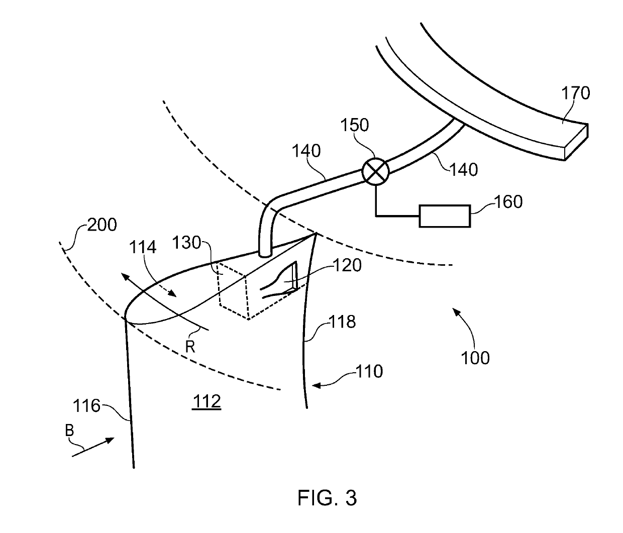
[0021]Providing the inlet on the bifurcation panel as described and / or claimed herein may increase the efficiency of the TCC system in comparison with conventional arrangements, for example by providing an improved driving pressure at the inlet to the TCC system. This may result in a TCC arrangement that can provide improved tip clearance control and / or reduced impact on engine efficiency.
[0022]Due to the rotation of the fan in use, and the resultant swirl in the bypass flow, the driving (or static) pressure on the first major surface in use may be higher than that on the second major surface. This may improve the effectiveness and / or efficiency of the TCC system.
[0023]The that is directed to the turbine casing by the tip clearance control system may be any temperature as required to provide control over the gap between the turbine blades and the turbine casing to be controlled. For example, the temperature of the air that is directed to the turbine casing by the tip clearance control system may be lower than the temperature of the core flow to which the turbine blades and turbine casing that is being cooled are exposed. The air that is delivered to the turbine casing by the tip clearance control system may be referred to as cooling air. The air that is delivered to the turbine casing by the tip clearance control system may be used to reduce the thermal growth of the casing and / or cool the casing and / or reduce to the diameter of the casing (relative to its diameter in the absence of the cooling air). The air passing into the inlet of the tip clearance control system may be cooler than the core flow to which the turbine blades and turbine casing that is being cooled are exposed.

Problems solved by technology

In use, gas turbine engines operate at high temperatures, which can lead to differential thermal expansion of components.
Leakage between the tip of a turbine blade and its shroud or casing can result in a significant reduction in the turbine's efficiency.
Consequences of contact between the blade tip and shroud can be life limiting for the components.
However, typically such air supply originates from another part of the gas turbine engine, and so may compromise the efficiency of the engine.

Method used


Image

  • Gas turbine engine offtake
  • Gas turbine engine offtake
  • Gas turbine engine offtake

Examples


Embodiment Construction

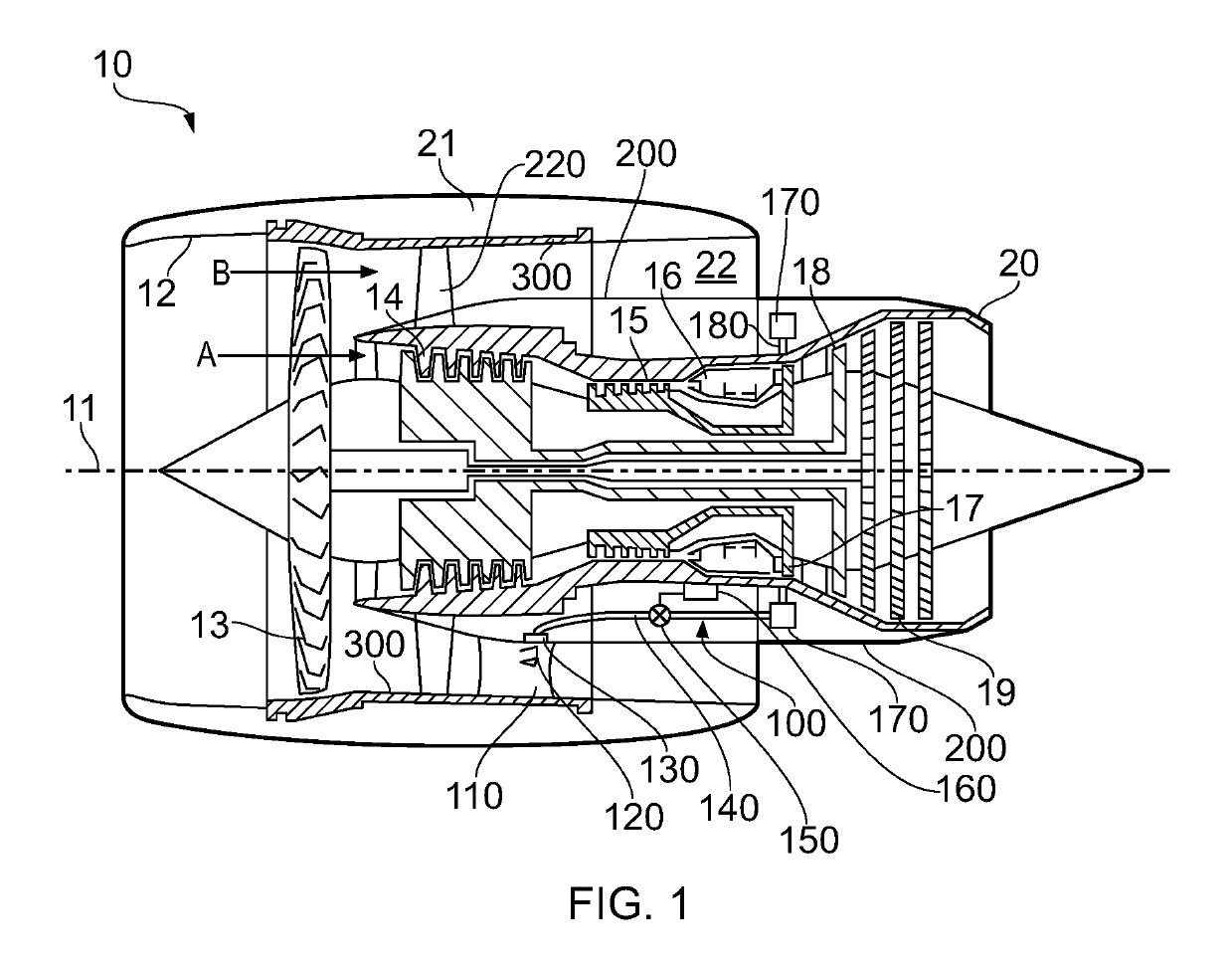
[0049]With reference to FIG. 1, a gas turbine engine is generally indicated at 10, having a principal and rotational axis 11. The engine 10 comprises, in axial flow series, an air intake 12, a propulsive fan 13, an intermediate pressure compressor 14, a high-pressure compressor 15, combustion equipment 16, a high-pressure turbine 17, an intermediate pressure turbine 18, a low-pressure turbine 19 and an exhaust nozzle 20. A nacelle 21 generally surrounds the engine 10 and defines both the intake 12 and the exhaust nozzle 20.

[0050]The gas turbine engine 10 works in the conventional manner so that air entering the intake 12 is accelerated by the fan 13 to produce two air flows: a first air flow A into the intermediate pressure compressor 14 and a second air flow B which passes through a bypass duct 22 to provide propulsive thrust. The intermediate pressure compressor 14 compresses the air flow directed into it before delivering that air to the high pressure compressor 15 where further ...


PUM


Abstract

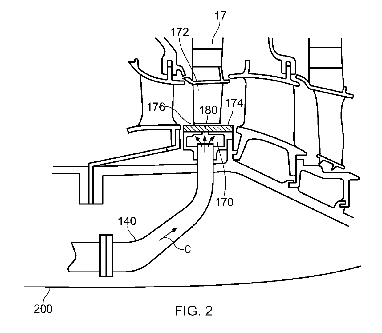
A tip clearance control (TCC) system 100 is provided to control the gap 176 between the tips of turbine blades 172 of a gas turbine engine 10 and the casing 174 within which they rotate. The inlet 120 to the TCC system is provided in a bifurcation panel 110 that extends across a bypass duct 22 of the gas turbine engine 10. The inlet is provided on a first major surface 112 of the bifurcation panel 110 that is defined such that the direction (R) that points through the bifurcation panel from the first major surface 112 to a second major surface 114 corresponds to the fan rotation direction. This provides a particularly effective and/or efficient TCC system 100.

Description

CROSS-REFERENCE TO RELATED APPLICATIONS[0001]This application is based upon and claims the benefit of priority from UK Patent Application Number 1720158.3 filed on 4 Dec. 2017, the entire contents of which are incorporated herein by reference.BACKGROUNDTechnical Field[0002]The present disclosure relates to a gas turbine having a tip clearance control system, and to a method of controlling the size of a gap between blades and a casing in a gas turbine engine.Description of the Related Art[0003]In use, gas turbine engines operate at high temperatures, which can lead to differential thermal expansion of components. The turbine section of a gas turbine engine can reach particularly high temperatures as it is downstream of the combustor, such that the dimension of a clearance space between the tip of a turbine blade and a shroud may vary during use depending on the operating condition. Leakage between the tip of a turbine blade and its shroud or casing can result in a significant reducti...

Claims


Application Information

Patent Timeline
Patent Type & Authority Applications(United States)
IPC IPC(8): F01D11/02F02C3/04F02C9/18
CPCF01D11/025F02C3/04F02C9/18F05D2240/55F01D9/041F01D9/06F01D11/24F01D17/105F05D2220/32F05D2250/51F05D2260/20Y02T50/60
Inventor HUSSAIN, ZAHID M.
Owner ROLLS ROYCE PLC
Why Eureka
Try Eureka