Antenna device
a technology of an antenna and a beam is applied in the field of an antenna device, which can solve the problems of inability to efficiently send and inability to avoid, so as to achieve the effect of efficiently sending an electromagnetic wave in a desired direction and insufficient precision in object detection
- Summary
- Abstract
- Description
- Claims
- Application Information
AI Technical Summary
Benefits of technology
Problems solved by technology
Method used
Image
Examples
first embodiment
Structure of the Antenna Device
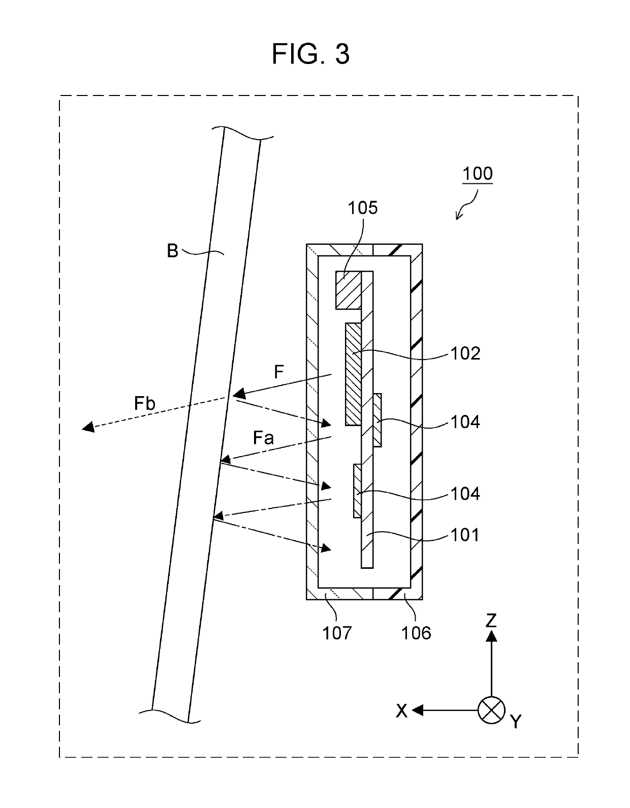
[0051]Reduction in the effects of the multi-reflection and turnaround wave described above will be described below.
[0052]FIG. 4 is a sectional side elevation of an antenna device U according to this embodiment. FIG. 5 is a front view of the antenna device U according to this embodiment when the front component side of a first circuit board part 1a is viewed from in front of the first circuit board part 1a). FIG. 6 is a plan view of the antenna device U according to this embodiment.
[0053]Each arrow F indicated by a solid line in FIGS. 4, 5, and 6 represents an electromagnetic wave sent from a transmission antenna 2. Each arrow Fr indicated by a dotted line in FIGS. 5 and 6 represents a reflected wave from the target. In FIGS. 4, 5, and 6, a structure that supports the antenna device U in the vehicle C is not illustrated.
[0054]The antenna device U according to this embodiment is applied to, for example, a radar device as with the antenna device 100 in th...
second embodiment
[0108]Next, an example of the structure of an antenna device U according to a second embodiment will be described with reference to FIG. 9.
[0109]FIG. 9 is a sectional side elevation of the antenna device U according to the second embodiment.
[0110]The antenna device U according to this embodiment differs from the antenna device U according to the first embodiment in that the antenna device U according to this embodiment has a bracket 8 that secures the case 6 and the like to the cover member B. Descriptions of structures common to the first embodiment and second embodiment will be omitted (this is also true for other embodiments described below).
[0111]The bracket 8 secures the case 6 to the cover member B to define a direction in which the antenna device U sends and receives an electromagnetic wave.
[0112]The bracket 8 has, for example, a storage portion 8a in which the antenna device U is stored and fixing portions 8b secured to the cover member B.
[0113]The storage portion 8a has, fo...
third embodiment
[0119]Next, an example of the structure of an antenna device U according to a third embodiment will be described with reference to FIG. 10.
[0120]FIG. 10 is a sectional side elevation of the antenna device U according to the third embodiment.
[0121]The antenna device U according to this embodiment differs from the antenna device U according to the first embodiment in that the antenna device U according to this embodiment has connecting parts 6b that thermally bond the case 6 to the circuit board 1 or circuit components mounted on the circuit board 1.
[0122]FIG. 10 illustrates a state in which the connecting parts 6b thermally bond the wall of the case 6 to the circuit board 1. Each hallow arrow T in the drawing represents a flow of heat from the circuit board 1.
[0123]In this embodiment, a metal member having a high heat dissipation property, for example, is used as the material of the case 6. Each connecting part 6b thermally bonds the wall of the case 6 to the circuit board 1 or circu...
PUM
 Abstract
Description
Claims
Application Information
 - R&D
- Intellectual Property
- Life Sciences
- Materials
- Tech Scout
- Unparalleled Data Quality
- Higher Quality Content
- 60% Fewer Hallucinations
Browse by: Latest US Patents, China's latest patents, Technical Efficacy Thesaurus, Application Domain, Technology Topic, Popular Technical Reports.
© 2025 PatSnap. All rights reserved.Legal|Privacy policy|Modern Slavery Act Transparency Statement|Sitemap|About US| Contact US: help@patsnap.com


