
Fuel cell system

a fuel cell and system technology, applied in the direction of battery/fuel cell control arrangement, battery/fuel cell propulsion, battery/cell control arrangement, etc., can solve the problems of secondary battery, excessive voltage of fuel cell, fuel cell progress, etc., to reduce the flow rate of compressed air, reduce the progress of drying of fuel cell or increase the potential of fuel cell.

Active Publication Date: 2019-05-30
TOYOTA JIDOSHA KK
View PDF0 Cites 2 Cited by
  • Summary
  • Abstract
  • Description
  • Claims
  • Application Information

AI Technical Summary

Benefits of technology

The patent provides a fuel cell system that can protect the fuel cell and secondary battery, while ensuring the generated power is close to the required power after auxiliary machine power consumption. The system includes an outlet valve that can be opened or closed based on the degree of opening of the bypass valve. This allows for easy control of the flow of compressed air into the fuel cell.

Problems solved by technology

Here, when all the regenerative power is assigned to charging of the secondary battery, there may be a problem in the secondary battery depending on the state of the secondary battery.
When auxiliary machine power consumption is carried out in an air compressor, compressed air is generated.
When all the compressed air is supplied to a fuel cell that is not performing power generation, drying of the fuel cell progresses and a voltage thereof increases excessively, whereby cells may be damaged.
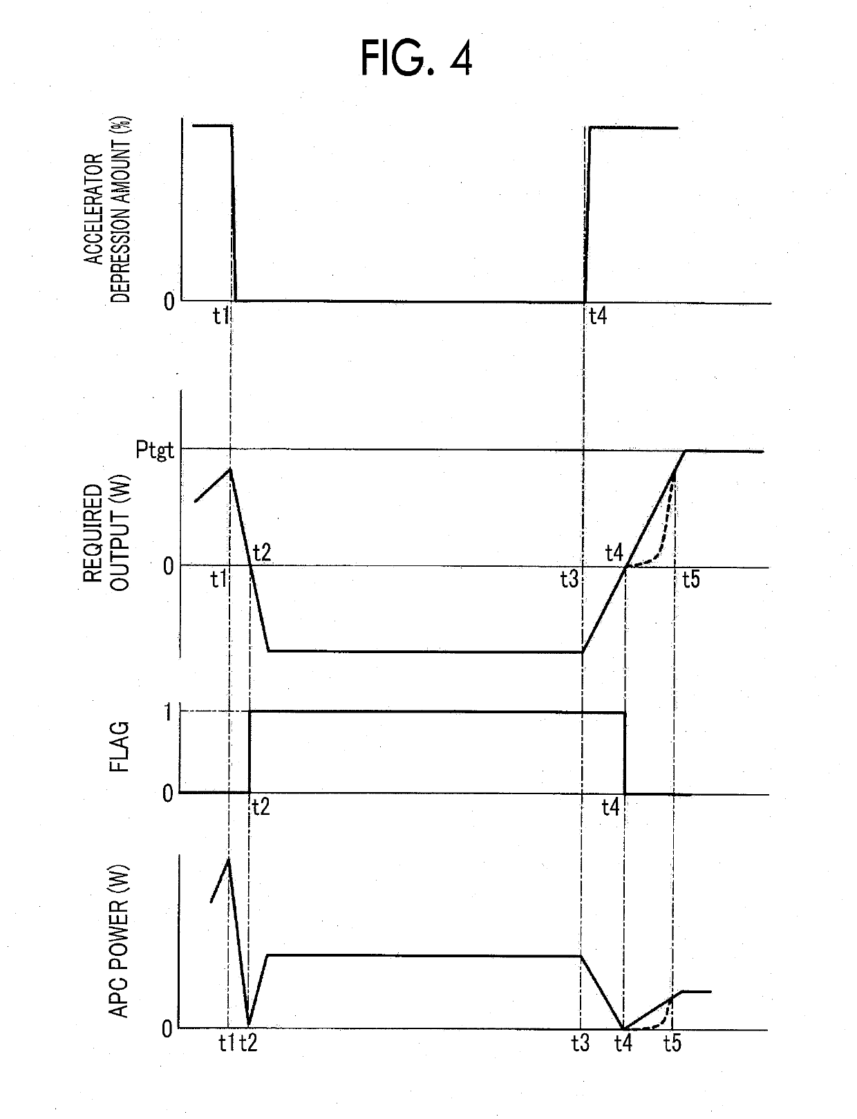
However, when compressed air does not flow into the fuel cell during execution of auxiliary machine power consumption, the voltage of the fuel cell may be excessively low at the time point at which the required output for the motor generator becomes a positive value.
However, since the generated power is small, necessary electric power cannot be supplied to the air compressor.
Accordingly, the voltage of the fuel cell increases slowly and the required power for the motor generator cannot be supplied.

Method used


Image

  • Fuel cell system
  • Fuel cell system
  • Fuel cell system

Examples


first embodiment

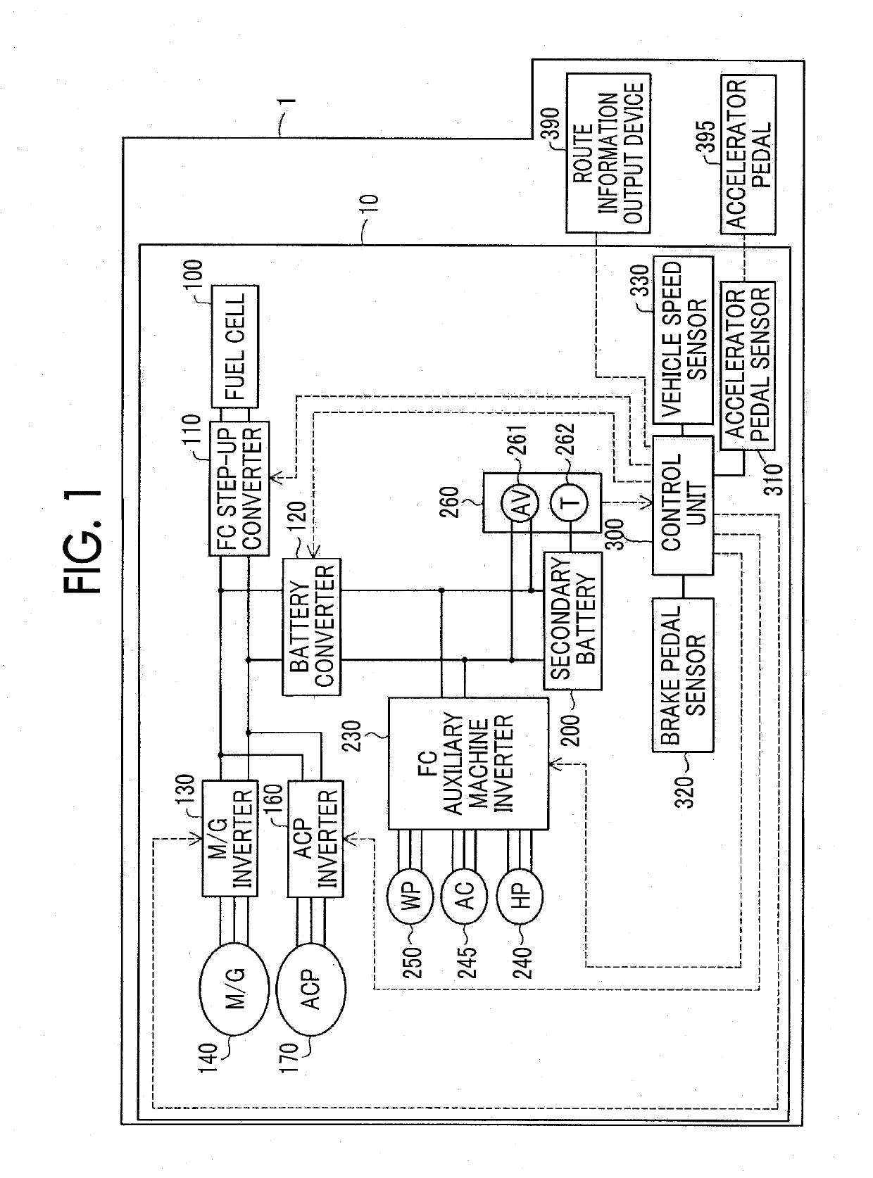
[0031]the disclosure will be described. FIG. 1 is a diagram schematically illustrating a configuration of an electrical system of a fuel cell system 10. The fuel cell system 10 is mounted in a vehicle 1 including a route information output device 390 and an accelerator pedal 395. The route information output device 390 is not used in this embodiment and thus will be described later.

[0032]The fuel cell system 10 includes a fuel cell 100, an FC step-up converter 110, a battery converter 120, an M / G inverter 130, an M / G 140, an ACP inverter 160, an air compressor 170, a secondary battery 200, an FC auxiliary-machine inverter 230, a hydrogen pump 240, an air-conditioning compressor 245, a coolant pump 250, a detection unit 260, a control unit 300, an accelerator pedal sensor 310, a brake pedal sensor 320, and a vehicle speed sensor 330.

[0033]In this embodiment, the air compressor 170, the hydrogen pump 240, and the coolant pump 250 are collectively referred to as auxiliary machine. The ...

second embodiment

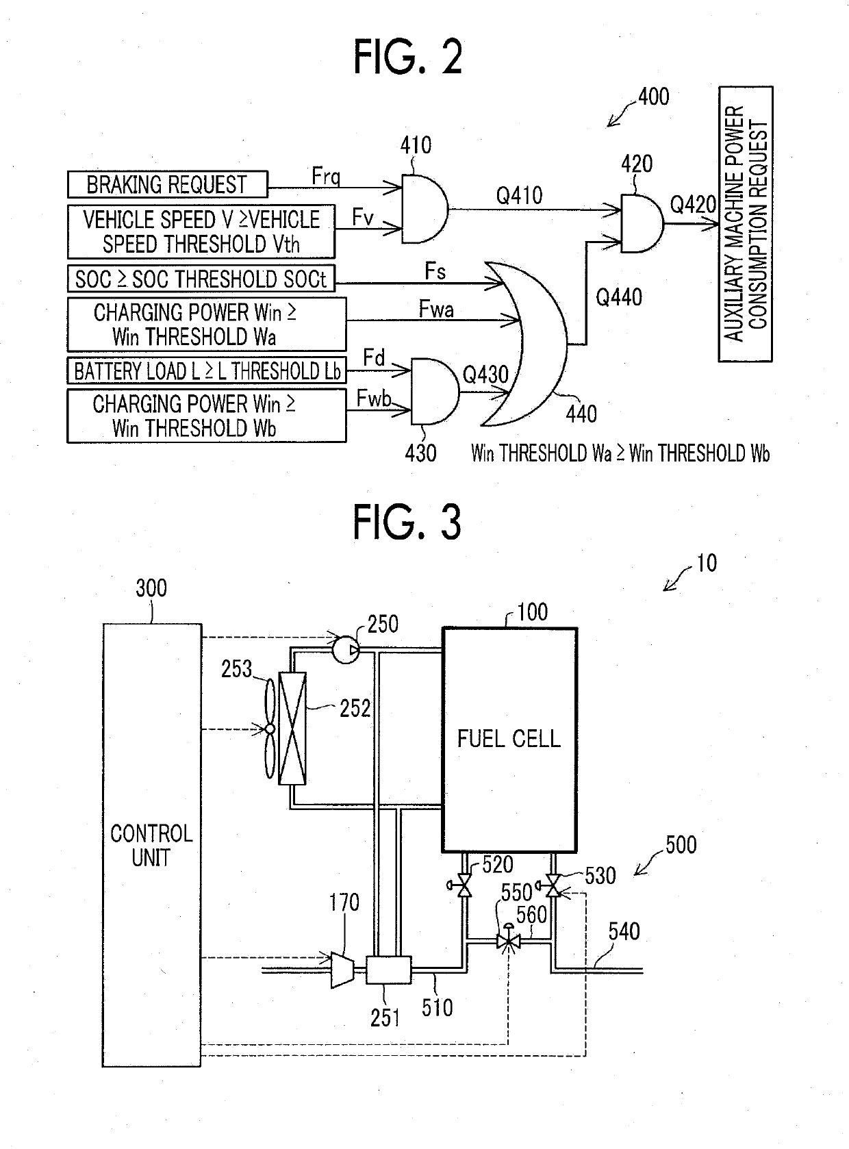
[0100]FIG. 8 is a flowchart illustrating a piping system setting process according to the First, the control unit 300 determines whether the FC voltage is lower than a target voltage Vtgt2 (S705). The target voltage Vtgt2 is a fixed value. The target voltage Vtgt2 is determined in advance as a value less than the high-potential avoidance voltage Vmax as illustrated in FIG. 5.

[0101]When the FC voltage is equal to or higher than the target voltage Vtgt2 (NO in S705), the control unit 300 sets the first state (S750).

[0102]On the other hand, when the FC voltage is lower than the target voltage Vtgt2 (YES in S705), the control unit 300 performs S710 and S720 as described in the first embodiment. When the determination result of S720 is NO, the control unit 300 sets the first state. When the determination result of S720 is YES, the control unit 300 sets the second state.

[0103]According to this embodiment which has been described above, calculation for changing the target voltage does not...

third embodiment

[0107]The route information includes information which can affect the required output. Information which can affect the required output is, for example, a road gradient or a radius of curvature of a curved road. The control unit 300 calculates the required output by combining such information. In the third embodiment, an amount of depression is not considered for calculating the required output. In another embodiment, the amount of depression may be considered for calculating the required output.

[0108]For example, when the vehicle travels on a road which changes rapidly from a downhill gradient to an uphill gradient, the control unit 300 predicts that the required output changes from a negative value to a positive value before the gradient changes from the downhill gradient to the uphill gradient.

[0109]Alternatively, for example, when an expressway is curved and then extends straightly, it is predicted that the required output is switched from a negative value to a positive value be...


PUM

PropertyMeasurementUnit
electric poweraaaaaaaaaa
voltageaaaaaaaaaa
power consumptionaaaaaaaaaa

Abstract

A control unit comprised in a fuel cell system is configured to perform prediction of whether a required output for a motor generator has a positive value and determination of whether a voltage of a fuel cell is less than a target voltage during execution of an auxiliary machine power consumption, and is configured to set a bypass valve to a first degree of opening during execution of the auxiliary machine power consumption when a result of at least one of the prediction and the determination is negative, and is configured to set the bypass valve to a second degree of opening less than the first degree of opening during execution of the auxiliary machine power consumption when results of both the prediction and the determination are positive.

Description

INCORPORATION BY REFERENCE[0001]The disclosure of Japanese Patent Application No. 2017-229148 filed on Nov. 29, 2017 including the specification, drawings and abstract is incorporated herein by reference in its entirety.BACKGROUND1. Technical Field[0002]The disclosure relates to auxiliary machine power consumption for consuming extra regenerative power.2. Description of Related Art[0003]In general, a fuel cell system which is mounted in a vehicle is configured to charge a secondary battery with regenerative power from a traveling motor generator. Here, when all the regenerative power is assigned to charging of the secondary battery, there may be a problem in the secondary battery depending on the state of the secondary battery. Japanese Unexamined Patent Application Publication No. 2017-135860 (JP 2017-135860 A) discloses that extra regenerative power is mainly consumed in an air compressor in this case.SUMMARY[0004]JP 2017-135860 A does not disclose control or phenomena near ending...

Claims


Application Information

Patent Timeline
Patent Type & Authority Applications(United States)
IPC IPC(8): H01M8/04858B60L1/00B60L11/18H01M8/0438H01M8/0432
CPCH01M8/04858B60L1/003B60L11/1803B60L11/1861B60L11/1887H01M8/0438H01M8/04358B60L2240/12B60L2240/36B60L2240/545B60L2240/547H01M2250/20B60L50/51B60L58/12B60L58/40H01M16/006H01M2220/20H01M8/04298Y02T90/40Y02T10/7072Y02T10/70Y02T90/14Y02E60/50Y02E60/10
Inventor MATSUO, JUNICHI
Owner TOYOTA JIDOSHA KK
Learn More