
Advanced flow bronchoscope

a flow bronchoscope and advanced technology, applied in the field of advanced flow bronchoscopes, can solve the problems of increasing the time and cost of the procedure, affecting the ability of ventilation, and pause the procedure and removing the device, so as to reduce the risk of patients, increase the oxygen supply, and reduce the need for pauses during procedures

Inactive Publication Date: 2019-05-30
UNIV OF UTAH RES FOUND
View PDF3 Cites 1 Cited by
  • Summary
  • Abstract
  • Description
  • Claims
  • Application Information

AI Technical Summary

Benefits of technology

The present invention is a bronchoscope that improves the delivery of oxygen to patients. It includes a hollow stainless steel tube with a series of branches that merge with the main shaft in different locations allowing for increased oxygen flow. The invention also includes a rotating adapter that improves airflow by positioning inserted tools so as not to block it. The invention may replace current rigid bronchoscopes as it reduces the need for pauses during procedures and provides improved care to patients. The adapter is designed to fit into various bronchoscope models.

Problems solved by technology

Physicians complain that the current design negatively affects ventilation capabilities.
Inefficient ventilation often results in pausing the procedure and removing the device until oxygen levels return to normal.
Such disturbances can increase the time and cost of the procedure as well as put the patient at more risk.
There are often abrasions of the respiratory tract caused by the insertion and removal of the bronchoscope.
The more the physician has to remove and reinsert the device, the greater the risk to the patient.

Method used


Image

  • Advanced flow bronchoscope
  • Advanced flow bronchoscope
  • Advanced flow bronchoscope

Examples


Embodiment Construction

[0025]Before any embodiments of the invention are explained in detail, it is to be understood that the invention is not limited in its application to the details of construction and the arrangement of components set forth in the following description or illustrated in the following drawings. The invention is capable of other embodiments and of being practiced or of being carried out in various ways.

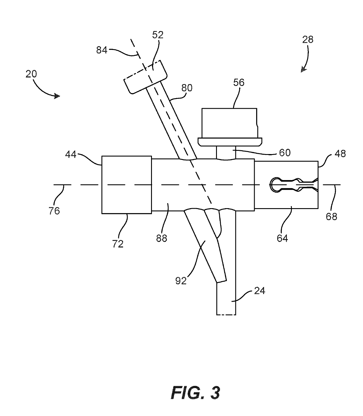
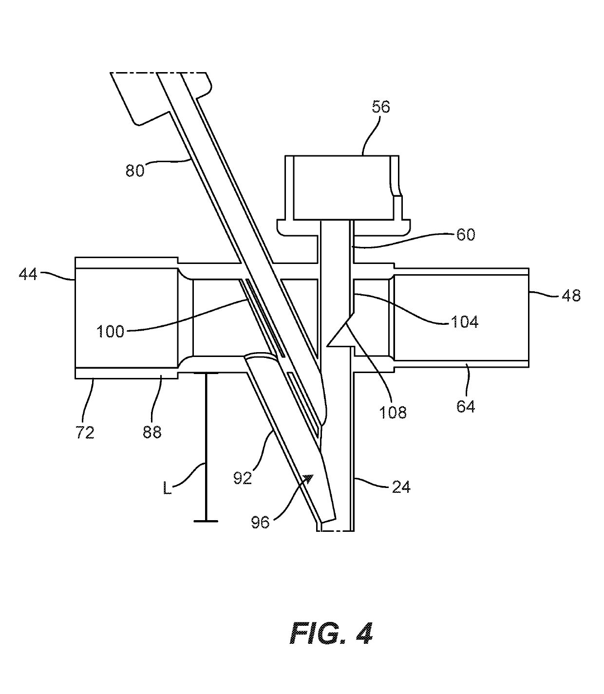
[0026]FIGS. 2-7 illustrate a bronchoscope 20 that optimizes oxygen delivery to a patient. The bronchoscope 20 includes a main shaft 24 defined by a hollow tube extending from a proximal end 28 to an open distal end 32 having a primary outlet aperture 36. The proximal end 28 includes a plurality of ports 40. In the illustrated embodiment, the proximal end 28 includes a plurality of access ports, for example, a ventilation port 44, a light or auxiliary port 48, a tool access port 52, and a main insertion port 56.

[0027]With reference to FIG. 3, the main insertion port 56 is engageable with a...


PUM


Abstract

A bronchoscope includes a main shaft extending from a proximal end to a distal end having an aperture. The proximal end of the bronchoscope includes a plurality of ports. One port is a ventilation port in fluid communication with the main shaft via a ventilation tube. The ventilation tube includes a first portion and a second portion, wherein the second portion extends from the first portion to the main shaft. The second portion is disposed at angle of approximately 60-70 degrees relative to the first portion. Another port may be configured to receive an adapter that includes a first member and a second member, wherein the second member is rotatable relative to the first member to relocate a tool received by the adapter within the main shaft.

Description

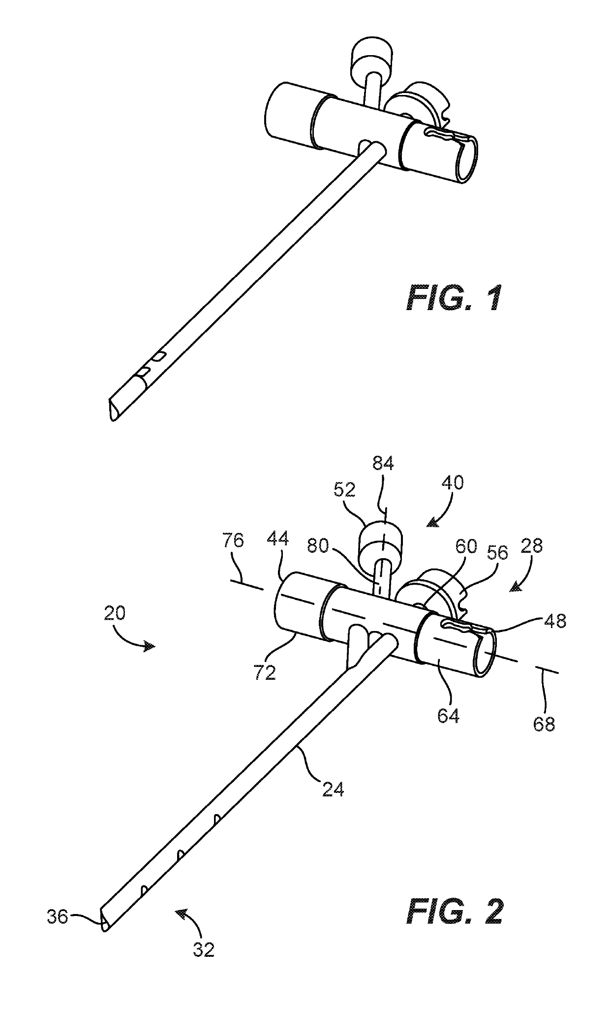
CROSS-REFERENCE TO RELATED APPLICATIONS[0001]This application is a non-provisional of and claims priority to U.S. Provisional Application No. 62 / 316,988, filed on Apr. 3, 2016, the contents of which are incorporated herein by reference.BACKGROUND OF THE INVENTION[0002]There are currently two methods of performing endoscopic procedures within the respiratory tract. One method uses a flexible scope and the other a rigid scope. The present invention relates to rigid scopes. Rigid scopes generally include a solid metal tube that branches at the proximal end into several ports. The main shaft provides access, airflow, and a place for anesthetic delivery.[0003]The majority of commercially available rigid bronchoscopes have a single union at the proximal end where the branches and main shaft merge (FIG. 1). Anything introduced to the system (e.g. light, oxygen, tools) must pass this single location. While several different bronchoscope designs exist, they all follow this same pattern. Phys...

Claims


Application Information

Patent Timeline
IPC IPC(8): A61M16/04A61B1/267A61B17/02A61B17/34
CPCA61M16/0463A61B1/2676A61B17/0218A61B17/3423A61B17/3462A61B2017/345A61B2017/00809A61B1/015A61B1/018A61B1/267
Inventor PARRY, TRENTTHORNLEY, KYLEBURTON, JOSHUANELSON, JOHNPARK, ALBERT
Owner UNIV OF UTAH RES FOUND
Learn More