
Enhanced expansion slot connector

a technology of expansion slot and computer bus, which is applied in the direction of fixed connection, coupling device connection, instruments, etc., can solve the problems and affecting the performance of the device. , to achieve the effect of reducing the physical footprint of the slot connector and achieving higher performance targets

Inactive Publication Date: 2019-05-02
SUPER MICRO COMP
View PDF5 Cites 0 Cited by
  • Summary
  • Abstract
  • Description
  • Claims
  • Application Information

AI Technical Summary

Benefits of technology

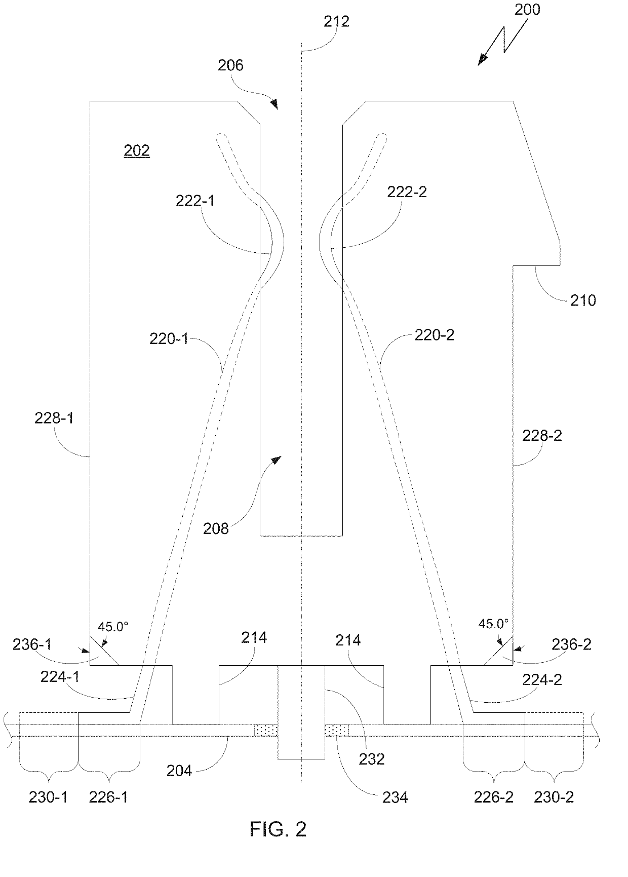
This patent is about reducing the size of a slot connector while still meeting certain standards and supporting high performance. This allows more components to be placed on a circuit board without interfering with each other.

Problems solved by technology

Transmissions become more prone to errors at higher speeds.
The through-hole mounting method is typically not able to handle the signal integrity needed to achieve the higher performance targets.
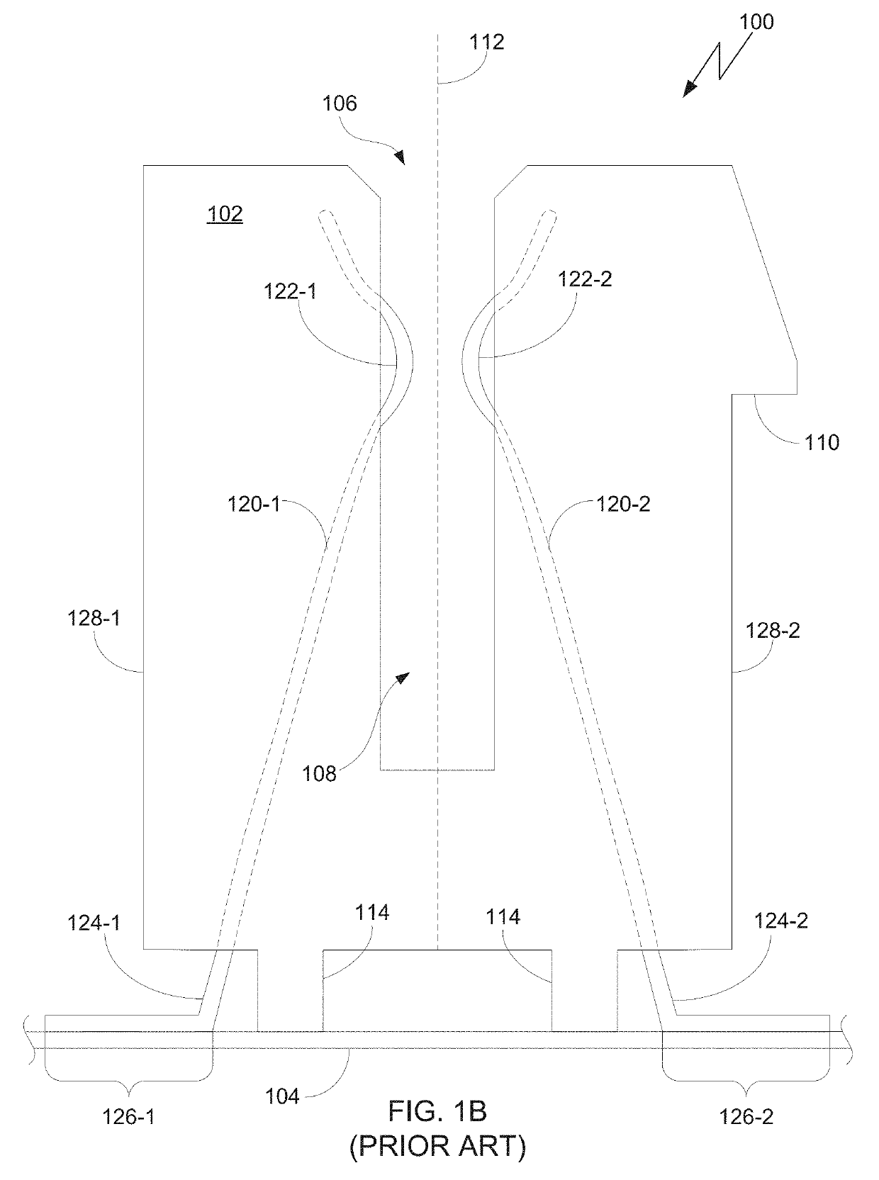
However, the surface mounting method poses challenges of its own, as a surface-mounted slot connector typically occupies a larger physical footprint in order to provide sufficient physical support for the slot connector.
This larger footprint can pose a challenge for designers of PCB layouts, including the layouts of riser cards.

Method used


Image

  • Enhanced expansion slot connector
  • Enhanced expansion slot connector
  • Enhanced expansion slot connector

Examples


Embodiment Construction

[0019]In the following description, numerous specific details are set forth to provide a more thorough understanding of the present invention. However, it will be apparent to one of skill in the art that the present invention may be practiced without one or more of these specific details.

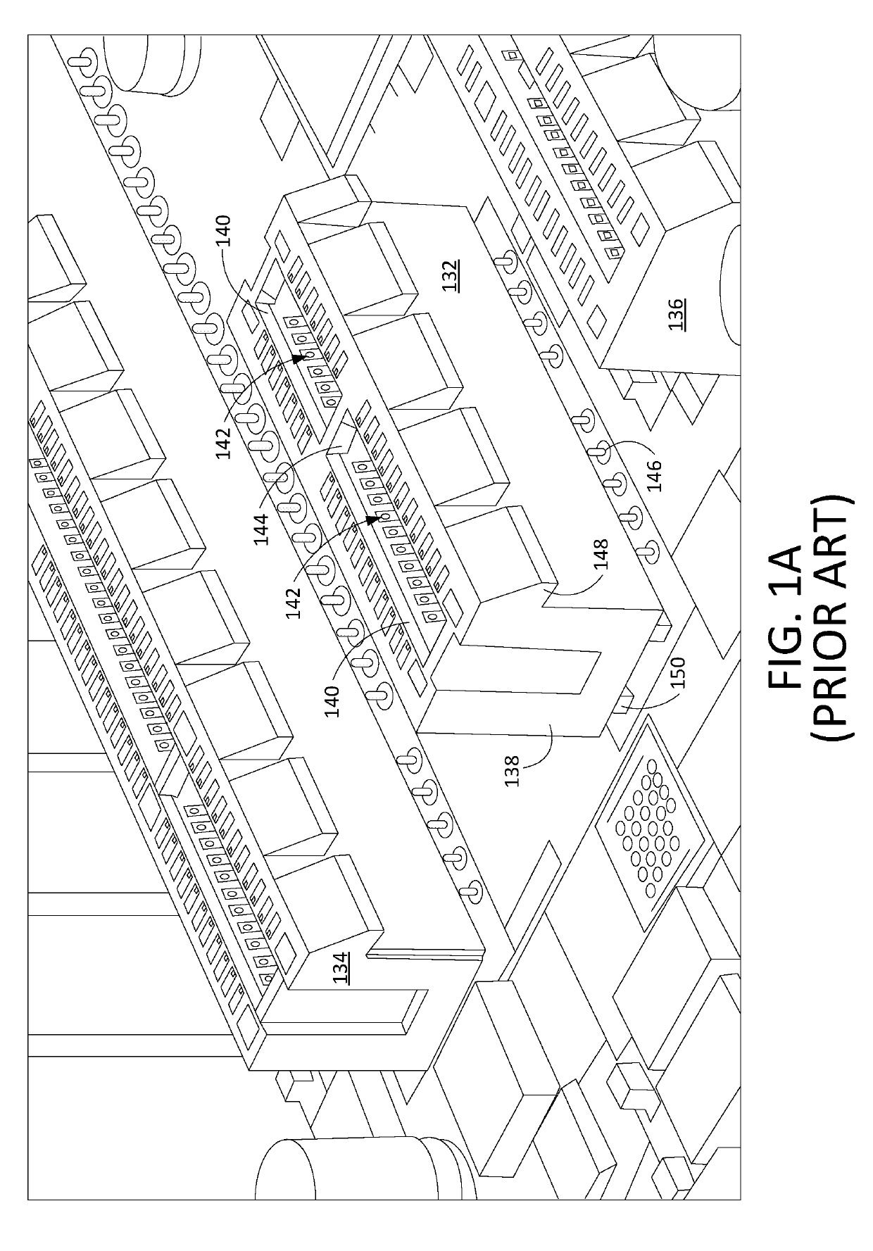
[0020]FIG. 1A is an image illustrating examples of conventional expansion slot connectors. The image shows three expansion slot connectors 132, 134, and 136. The image shows a complete view of slot connector 132, and partial views of slot connectors 134 and 136.

[0021]Each of the three slot connectors 132, 134, and 136 has a connector body with an opening at the top of the connector body. For example, slot connector 132 has a connector body 138 with an opening 140 at the top side of the connector body 138. The opening 140 runs lengthwise along the connector body 138. The opening 140 opens into a recessed area 142 of the connector body 138 that also runs lengthwise along the connector body 138. The re...


PUM


Abstract

An expansion slot connector has length-reduced termination portions for surface-mounting onto a printed circuit board, while maintaining compliance with defined standards, manufacturer specifications, and signal integrity demands. At least one advantage in this approach is that the physical footprint of the slot connector is reduced.

Description

BACKGROUND OF THE INVENTIONField of the Invention[0001]Embodiments of the present invention relate generally to computer buses, and, more specifically, to an enhanced computer bus expansion slot connector.Description of the Related Art[0002]The functionality of a computer system may be expanded through the use of expansion cards. One or more expansion slot connectors may be mounted onto a printed circuit board (PCB), such as a motherboard, in a computer system. An expansion card may be attached to the computer system via insertion into a slot connector. The expansion slot connector is connected to a computer bus in the computer system, and thus couples the expansion card to the computer bus. An expansion slot connector may be mounted onto the PCB by any of several methods, for example by through-hole mounting or surface mounting the conductive leads of the slot connector to the PCB.[0003]Various computer bus standards have been defined, and a standard may have multiple revisions, wi...

Claims


Application Information

Patent Timeline
Patent Type & Authority Applications(United States)
IPC IPC(8): H01R12/71H01R13/6473H01R12/70
CPCH01R12/716H01R13/6473H01R12/7052H01R2201/06G06F1/185G06F1/186H01R12/57H01R12/707H01R12/737
Inventor TENG, TERRYHUANG, TE
Owner SUPER MICRO COMP
Learn More