Actuator, optical device, and projector
a technology of optical devices and projectors, applied in the direction of optics, projectors, instruments, etc., can solve the problems of complex structure, specks may occur, and complicated movement, and achieve the effect of excellent image display
- Summary
- Abstract
- Description
- Claims
- Application Information
AI Technical Summary
Benefits of technology
Problems solved by technology
Method used
Image
Examples
first exemplary embodiment
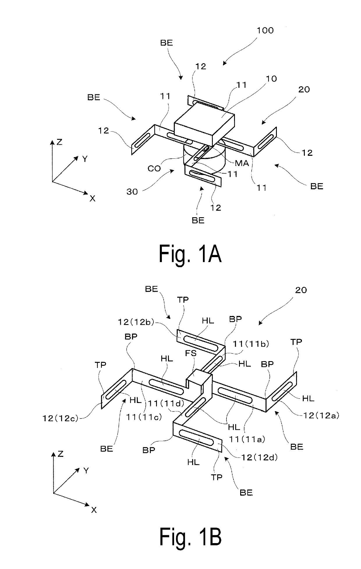
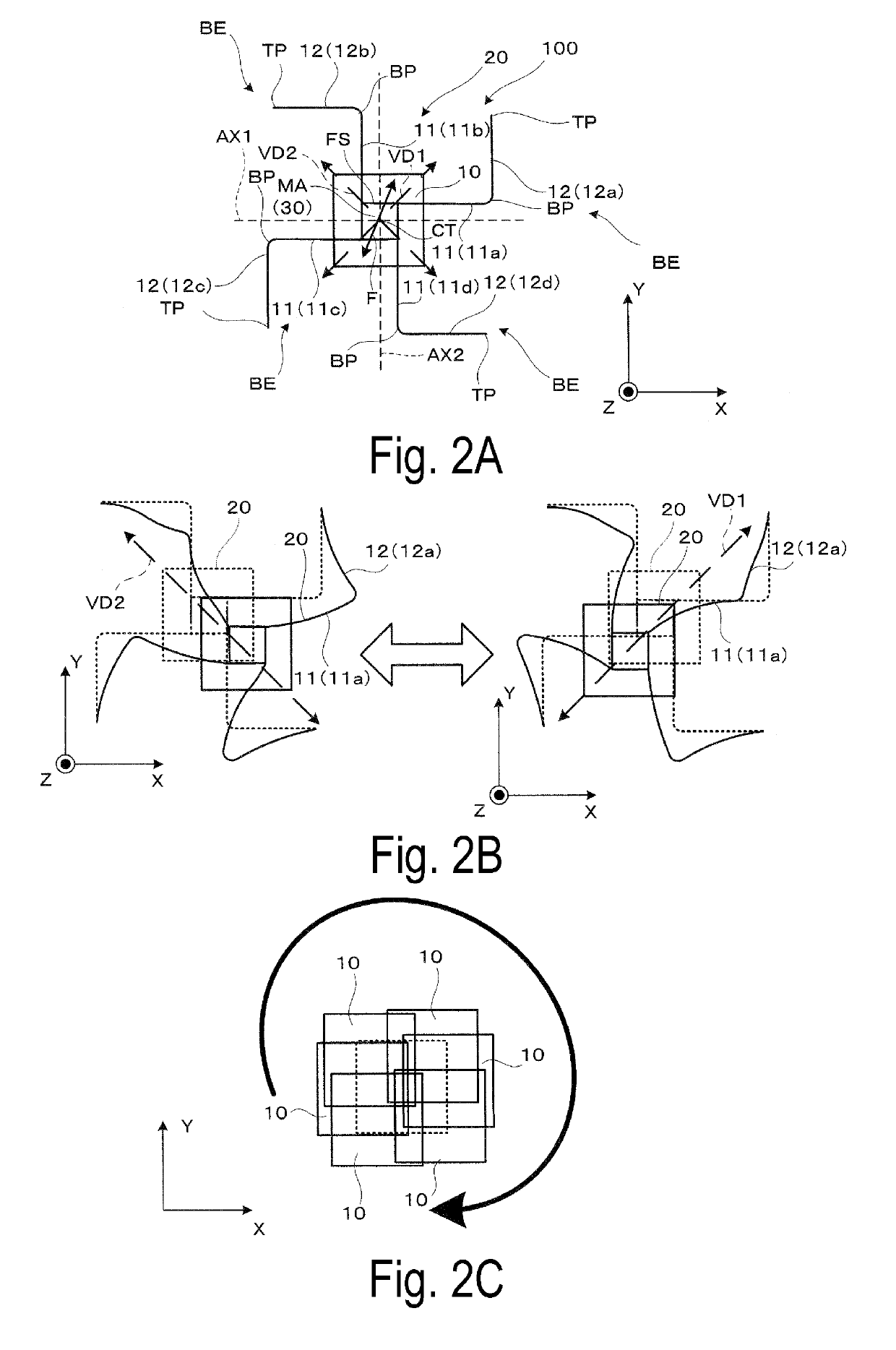
[0040]Hereinafter, an example of an actuator according to First Exemplary Embodiment will be described in detail with reference to FIGS. 1A and 1B and the like.
[0041]As illustrated in FIGS. 1A and 1B, an actuator 100 in First Exemplary Embodiment includes a movable portion 10, a beam structural portion 20 on which the movable portion 10 is mounted and fixed and which is configured to transmit vibration, and a driving portion 30 configured to drive the movable portion 10 via the beam structural portion 20.
[0042]First, in the actuator 100, the movable portion 10 is a member including a plane portion (rectangular surface portion in the drawing), and, for example, the movable portion 10 is a driven portion including an optical element such as a light diffusion plate attached to the plane portion, and being movable by being driven by the driving portion 30 and the like. It is assumed here that the plane portion of the movable portion 10 is a reference surface (horizontal surface), and, a...
second exemplary embodiment
[0060]Hereinafter, an actuator according to Second Exemplary Embodiment will be described with reference to FIGS. 5A and 5B and the like. Second Exemplary Embodiment is a modification of First Exemplary Embodiment. The actuator according to Second Exemplary Embodiment is the same as the actuator according to First Exemplary Embodiment, except for a structure of a beam structural portion and disposition of a driving portion, and thus the same reference signs are assigned to members having the same functions, and detailed description of each portion will be omitted.
[0061]As illustrated in FIGS. 5A and 5B, an actuator 200 according to Second Exemplary Embodiment includes a movable portion 10, a beam structural portion 220 on which the movable portion 10 is mounted and fixed and which is configured to transmit vibration, and a driving portion 230 configured to drive the movable portion 10 via the beam structural portion 220.
[0062]Hereinafter, a structure of the beam structural portion 2...
third exemplary embodiment
[0071]Hereinafter, an optical device in which the above-described actuator is installed and a projector according to Third Exemplary Embodiment will be described with reference to FIG. 7. Here, an optical device 900 in which the actuator 100 exemplified in First Exemplary Embodiment is installed is exemplified, but another actuator may be installed.
[0072]A projector 800 illustrated in FIG. 7 includes a light source device 700 configured to eject laser light, an image formation optical system 300, and a projection optical system 600.
[0073]The light source device 700 includes a light source 710 and the like in addition to the optical device 900 in which the actuator 100 is installed.
[0074]Here, the optical device 900 in Third Exemplary Embodiment is a device including a light diffusion plate DP as an optical element at a place of the movable portion 10 of the actuator 100 configured to cause the light diffusion plate DP to make curvilinear motion and to appropriately disturb and refle...
PUM
 Abstract
Description
Claims
Application Information
 - R&D
- Intellectual Property
- Life Sciences
- Materials
- Tech Scout
- Unparalleled Data Quality
- Higher Quality Content
- 60% Fewer Hallucinations
Browse by: Latest US Patents, China's latest patents, Technical Efficacy Thesaurus, Application Domain, Technology Topic, Popular Technical Reports.
© 2025 PatSnap. All rights reserved.Legal|Privacy policy|Modern Slavery Act Transparency Statement|Sitemap|About US| Contact US: help@patsnap.com


