Display device and display method thereof
A technology for a display device and a display part, which is applied to static indicators, instruments, etc., can solve the problems of reduced brightness and reduced transmittance, and achieve the effect of good color reproducibility
- Summary
- Abstract
- Description
- Claims
- Application Information
AI Technical Summary
Problems solved by technology
Method used
Image
Examples
Embodiment approach 1
[0077]
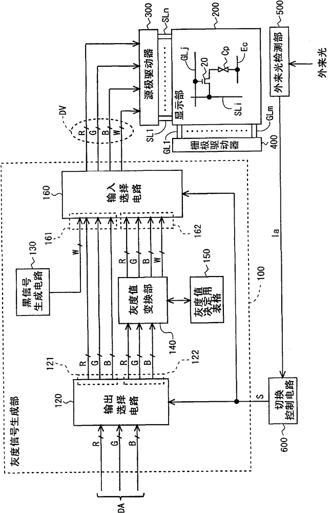
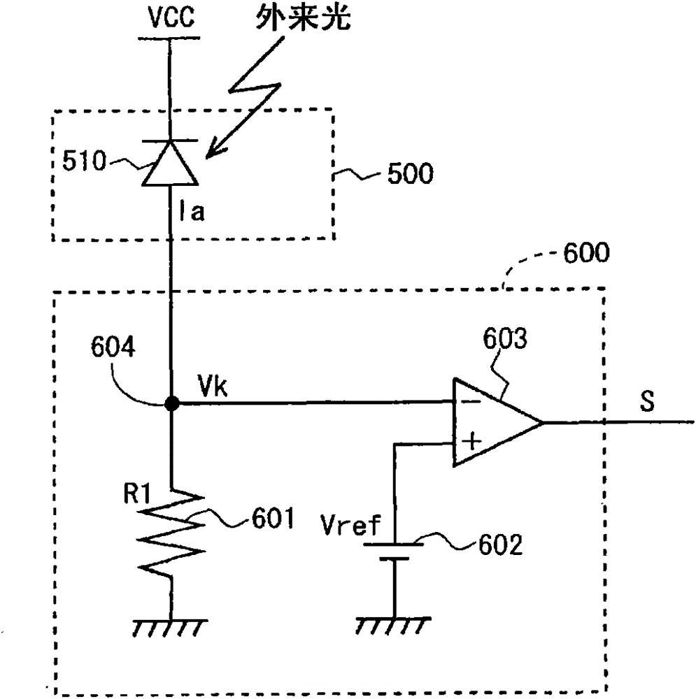
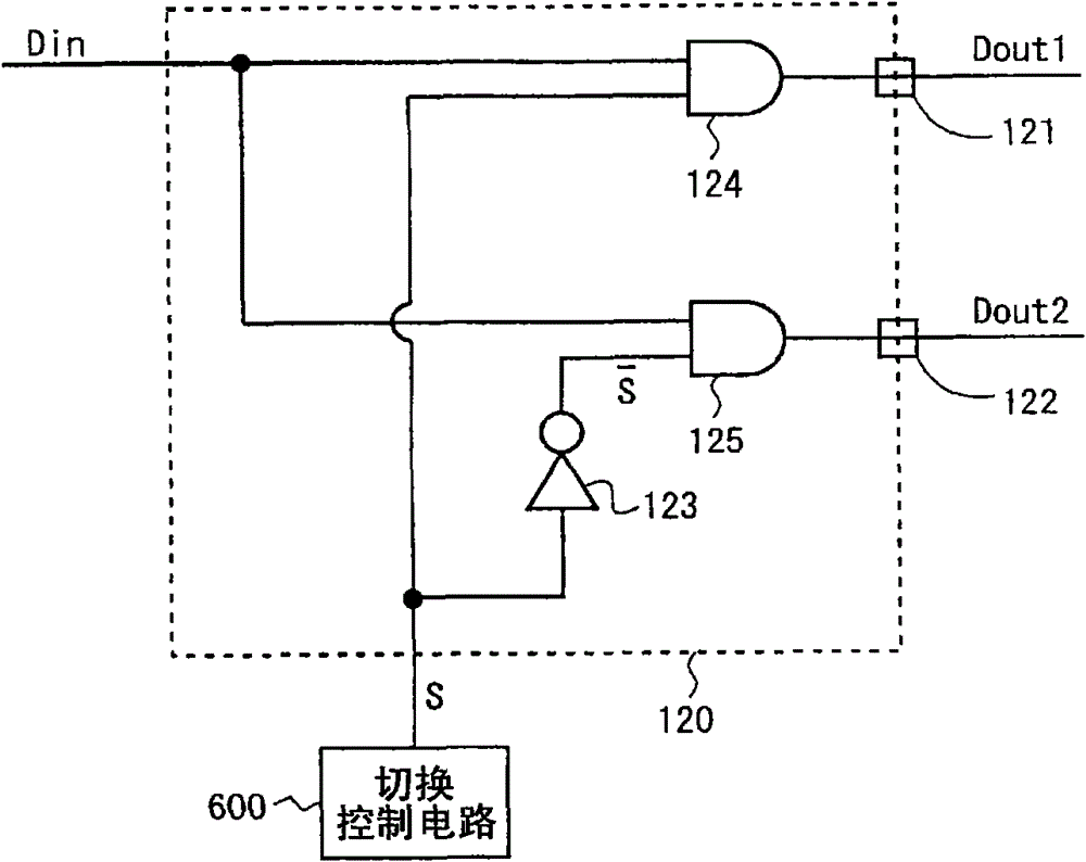
[0078] figure 1 It is a block diagram showing the overall configuration of the liquid crystal display device according to Embodiment 1 of the present invention. This liquid crystal display device has a gradation signal generating unit 100, a display unit (display panel) 200, a source driver (video signal line driving circuit) 300, a gate driver (scanning signal line driving circuit) 400, an extraneous light detecting unit 500 and Switch control circuit 600 .
[0079] The display unit 200 includes: multiple (n) source bus lines (video signal lines) SL1˜SLn; multiple (m) gate bus lines (scanning signal lines) GL1˜GLm; A plurality of (n×m) pixel forming portions provided at intersections of SL1 to SLn and a plurality of gate bus lines GL1 to GLm. These pixel forming portions are arranged in a matrix to form a pixel array. In addition, each pixel forming portion forms one of predetermined colors of R (red), G (green), B (blue), or W (white). That is, in this embodi...
example 1
[0125] In Embodiment 1 described above, when the second display mode is performed, the RGBW image signal used for image display is generated by referring to the gradation value determination table 150 in the gradation value conversion unit 140 . However, the present invention is not limited thereto. In a liquid crystal display device having RGBW four-color sub-pixels, the grayscale value indicated by the digital image signal DA transmitted from the outside may be used as it is for the three primary colors of RGB as the grayscale value at the time of image display. In this case, it is not necessary for the gradation value conversion unit 140 to generate an image signal for the three colors of RGB among the four colors of RGBW. Therefore, the structure between the second output terminal group 122 of the output selection circuit 120 and the second input terminal group 162 of the input selection circuit 160 can also be adopted Figure 7 structure shown. In this configuration, th...
example 2
[0127] In addition, in the first embodiment described above, when performing the second display mode, the gradation value determination table referred to by the gradation value conversion unit 140 is only one, but the present invention is not limited to this. E.g Figure 9 As shown, a structure in which three tables (the first grayscale value determination table 152, the second grayscale value determination table 153, and the third grayscale value determination table 154) are referred to by the grayscale value conversion unit 142 may also be employed. . In addition, in this configuration, in order to determine the table to be referred to by the gradation value converting unit 142 , a 2-bit display mode selection signal S is supplied to the gradation value converting unit 142 . At this time, it is only necessary to set the value of each bit of the display mode selection signal S according to the intensity of the external light, for example Figure 10 shown. Therefore, the ou...
PUM
 Abstract
Description
Claims
Application Information
 - R&D
- Intellectual Property
- Life Sciences
- Materials
- Tech Scout
- Unparalleled Data Quality
- Higher Quality Content
- 60% Fewer Hallucinations
Browse by: Latest US Patents, China's latest patents, Technical Efficacy Thesaurus, Application Domain, Technology Topic, Popular Technical Reports.
© 2025 PatSnap. All rights reserved.Legal|Privacy policy|Modern Slavery Act Transparency Statement|Sitemap|About US| Contact US: help@patsnap.com


