Head unit

a head unit and head technology, applied in the direction of inking apparatus, coupling device connection, fixed connection, etc., can solve the problem of difficulty in providing sufficient electric power for driving all piezoelectric elements, and achieve the effect of reducing noise interference and improving liquid discharge accuracy

Active Publication Date: 2019-05-02
SEIKO EPSON CORP
View PDF0 Cites 2 Cited by
  • Summary
  • Abstract
  • Description
  • Claims
  • Application Information

AI Technical Summary

Benefits of technology

The invention aims to provide a head unit that can minimize the issues that arise with a high density of nozzles.

Problems solved by technology

However, in accordance with the increase in the density of nozzles and the number of nozzles, there is a possibility that the discharge characteristics among the nozzles vary due to generation of deviation of an ink pressure in each nozzle, and further, in a wiring of the related art, a new problem that it is difficult to supply sufficient electric power for driving all of the piezoelectric elements.

Method used


Image

  • Head unit
  • Head unit
  • Head unit

Examples


first embodiment

1. Configuration of Liquid Discharge Apparatus 1

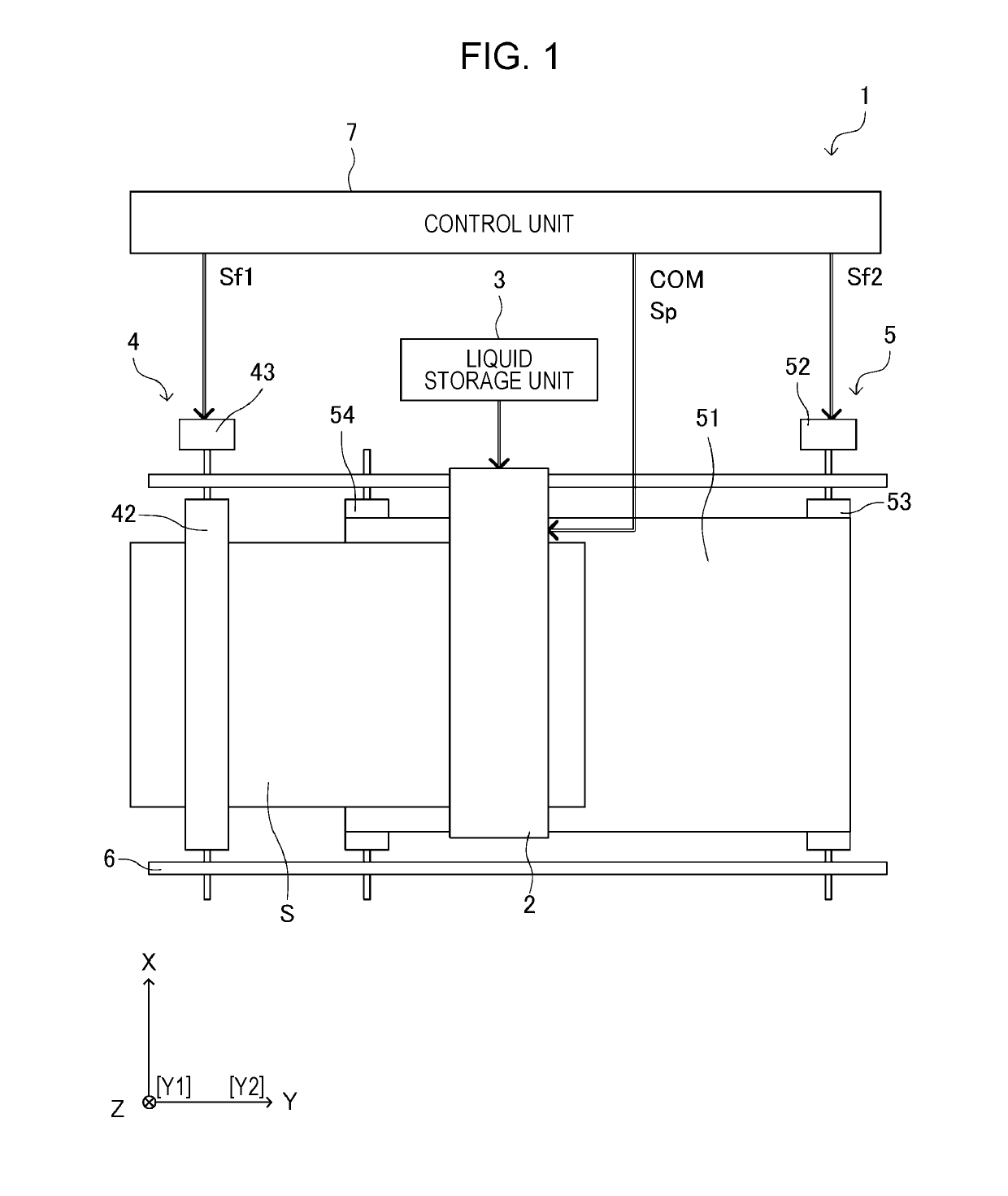
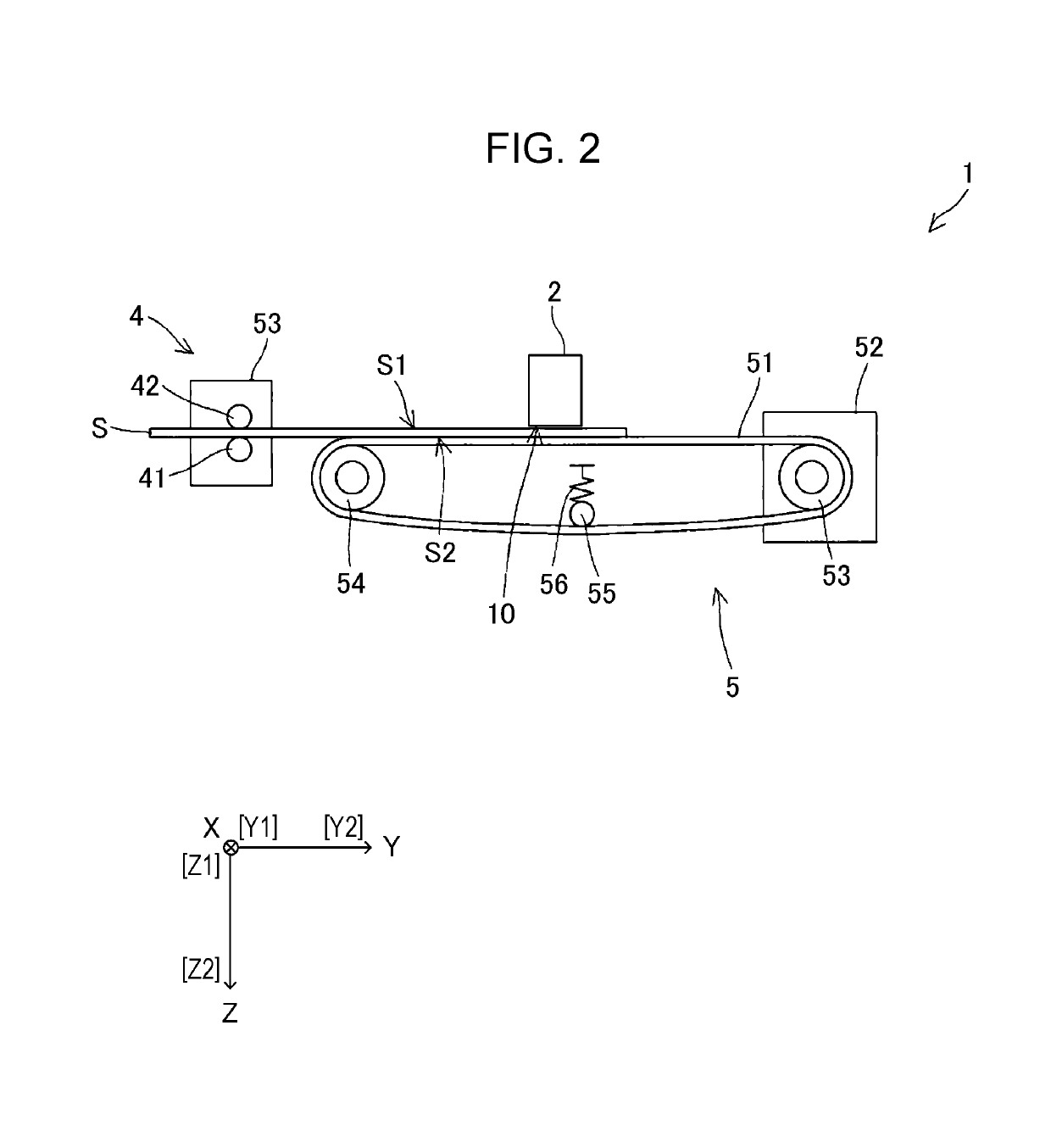
[0075]FIG. 1 is a top view illustrating a schematic configuration of a liquid discharge apparatus 1 according to a first embodiment. In addition, FIG. 2 is a side view illustrating a schematic configuration of the liquid discharge apparatus 1. The liquid discharge apparatus 1 is a so-called line type ink jet type recording apparatus that performs printing only by transporting a recording sheet S that is a recording medium.

[0076]In the first embodiment, in the liquid discharge apparatus 1, a direction in which the recording sheet S is transported is as a direction Y, a direction which is orthogonal to the direction Y and parallel to a surface of the recording sheet S is a direction X, a direction which is perpendicular to a plane (X-Y plane) parallel to the surface of the recording sheet S and in which ink (liquid) is discharged from a nozzle of a print head 2 is a direction Z. In addition, in the direction Y, an upstream side of a tran...

second embodiment

[0200]Hereinafter, the head unit 20 of a second embodiment will be described. The head unit 20 of the second embodiment will mainly describes the contents different from those of the first embodiment, and the description of contents that overlap those of the first embodiment will be omitted. In addition, in the head unit 20 of the second embodiment, the description will be made while the same reference numerals will be given to the same configuration elements as those of the first embodiment.

[0201]FIG. 12 is a perspective view of the head unit 20 in the second embodiment. In addition, FIG. 13 is a sectional view taken along the line XIII-XIII of FIG. 7 in the second embodiment.

[0202]The head unit 20 of the second embodiment is different from that of the first embodiment in that the wiring substrates 311, 312, 313, 314, and 315 which connect the substrate units 220, 230, 240, and 250 to each other are provided between each of the substrate units 220, 230, 240, and 250 and the passage...


PUM


Abstract

There is provided a head unit including: a first substrate provided with a first terminal and a second terminal; a second substrate provided with a third terminal; a first flexible wiring substrate that connects the first terminal and the third terminal to each other; a first driving module that is electrically connected to the second substrate; a third substrate provided with a fourth terminal; a second flexible wiring substrate that connects the second terminal and the fourth terminal to each other; a second driving module that is electrically connected to the third substrate; and a liquid flow passage which is positioned between the second substrate and the third substrate, and supplies the liquid to the first driving module and the second driving module, in which the first substrate is positioned on the second substrate side in a direction intersecting with a direction in which a liquid is discharged.

Description

[0001]The entire disclosure of Japanese Patent Application No. 2017-211018, filed Oct. 31, 2017 is expressly incorporated by reference herein.BACKGROUND1. Technical Field[0002]The present invention relates to a head unit.2. Related Art[0003]As an ink jet printer for printing an image or a document by discharging a liquid, such as ink, a printer using a piezoelectric element (for example, a piezo element) is known. A piezoelectric element is provided in accordance with each of a plurality of nozzles in a print head, each of the piezoelectric elements is driven according to a driving signal, and accordingly, a predetermined amount of liquid is discharged from the nozzles at a predetermined timing to form dots on a medium. Since the piezoelectric element is a capacitive load, such as a capacitor, in terms of electricity, it is necessary to supply a sufficient current in order to operate the piezoelectric element of each of the nozzles.[0004]Japanese Patent No. 5181898 and JP-A-2011-207...

Claims


Application Information

Patent Timeline
Patent Type & Authority Applications(United States)
IPC IPC(8): B41J2/14H05K1/14
CPCB41J2/14209H05K1/147H01R12/62H01R12/79B41J2002/14491B41J2/14233B41J2202/19B41J2202/20B41J2/14274B41J2/01H10K59/131H10K71/60H10N30/802H10N30/875H10N30/2047
Inventor KITAZAWA, KOJITSUYUKI, MASAHIKO
Owner SEIKO EPSON CORP
Why Eureka
Try Eureka