
Display with a waveguide coated with a meta-material

a technology of waveguide and meta-material, which is applied in the field of display with waveguide coated with a meta-material, can solve the problems of significant limitation of the total field of view of the input light into the waveguide of the display apparatus, the angular limitation of tir within the waveguide, and the colour variation of the total field of view of the input light into the waveguide at different colours of light, so as to enhance the field of view of the waveguide optical display apparatus

Active Publication Date: 2019-04-25
BAE SYSTEMS PLC
View PDF2 Cites 12 Cited by
  • Summary
  • Abstract
  • Description
  • Claims
  • Application Information

AI Technical Summary

Benefits of technology

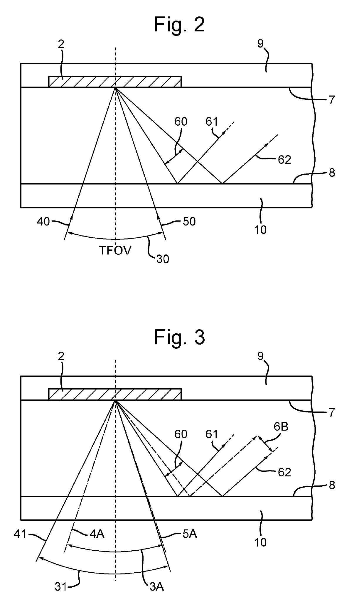
The invention enhances the field of view of a waveguide optical display apparatus by coating the waveguide with a material having a refractive index of about 1, which reduces geometrical distortions on image-bearing light. The preferred conjugation of the second diffractive part helps to reversing the distortions imposed by the first switchable diffractive part, and also reduces chromatic dispersion. This is especially beneficial when a broadband optical source, such as an LED light source, is employed as the light input to the waveguide.

Problems solved by technology

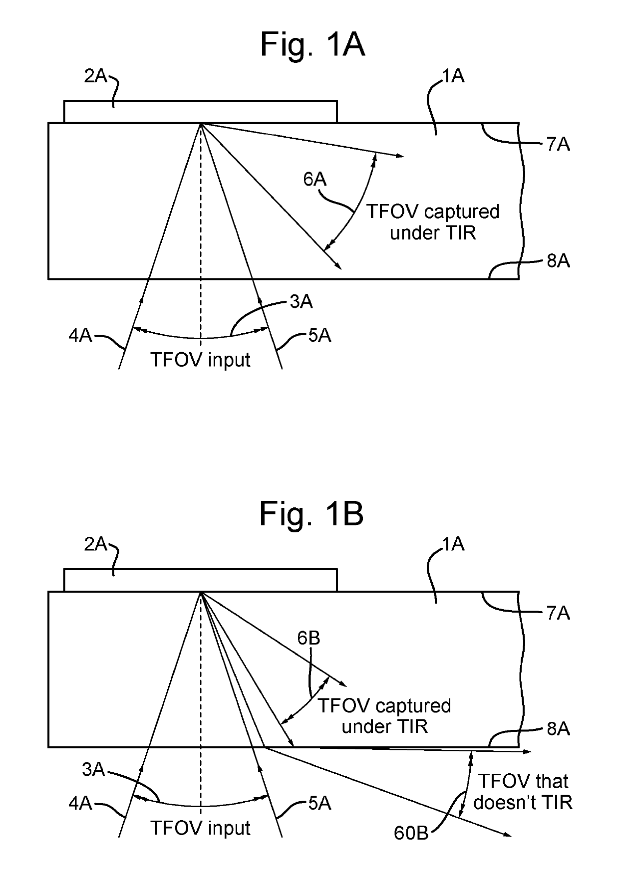
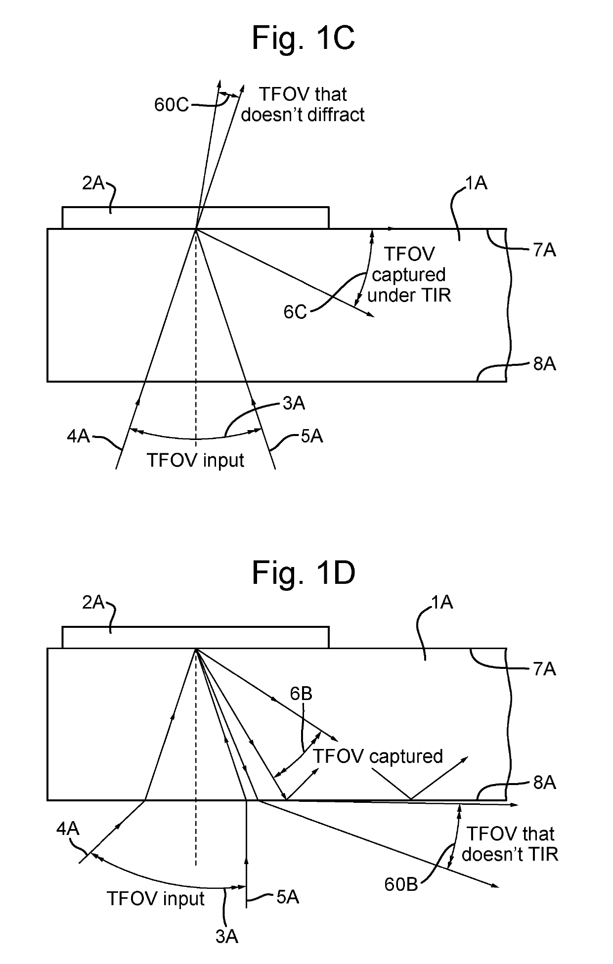
Optical waveguides for display devices of this type typically present a field of view (FOV) which is dictated by, and limited according to, the ability of the waveguide to retain light injected into it for propagation along the waveguide by total internal reflection (TIR).
This angular limitation for TIR within the waveguide is in respect of a particular (first) wavelength of light to which the structure of the Bragg grating is tuned.
The result is that some of the light of the second wavelength entering the apparatus at and close to one of the extreme angular positions (4A) is subsequently diffracted by the Bragg grating to an angle within the waveguide (1A) which will not allow TIR of that light.
This colour variation of the total field of view of the input light into the waveguide of the display apparatus, at different colours of light, is a significant limitation.
This total field of view of the input light into the waveguide of the display apparatus is a significant limitation.

Method used


Image

  • Display with a waveguide coated with a meta-material
  • Display with a waveguide coated with a meta-material
  • Display with a waveguide coated with a meta-material

Examples


Embodiment Construction

[0029]In the drawings like articles are assigned like reference symbols.

[0030]FIGS. 2 and 3 schematically illustrate a cross-sectional view of the input end of a slab waveguide for a display apparatus according to a preferred embodiment of the invention. The input end illustrated in each of these figures is shown as part of the complete optical waveguide apparatus illustrated schematically in FIG. 4.

[0031]The apparatus includes an optical waveguide (1) in the form of a slab waveguide upon a rear surface of which is formed an input Bragg grating (2) arranged and tuned for diffracting light of given wavelengths (e.g. visible light) input to the optical waveguide via an opposing surface (8) of the slab waveguide. The diffractive grating structure of the input Bragg grating (2) is arranged into an angle for guided propagation along the optical waveguide such that input light (40, 50) impinging upon the diffractive surface of the input Bragg grating is diffracted into a first diffraction...


PUM


Abstract

An apparatus is disclosed for producing an optical display comprising an optical waveguide including a first diffractive part arranged to receive display light and to diffract the display light into an angle for guided propagation along the optical waveguide. A second diffractive part of the waveguide is optically coupled to the first diffractive part by the optical waveguide and is arranged to receive and to diffract light from the first diffractive part to an angle for output from the optical waveguide. Those external surfaces of the waveguide against which guided light reflects internally are coated with a meta-material having a refractive index of value less than 1.0 (one).

Description

FIELD OF THE INVENTION[0001]The invention relates to a method and apparatus for providing an optical display such as, but without limitation to, an optical display employing an optical waveguide. In particular, the invention is relevant to a display device in which image-bearing light is injected into the waveguide and is subsequently released from the waveguide for viewing.BACKGROUND[0002]Optical waveguides for display devices of this type typically present a field of view (FOV) which is dictated by, and limited according to, the ability of the waveguide to retain light injected into it for propagation along the waveguide by total internal reflection (TIR). If light is injected into the waveguide outside of a particular angular range, then it cannot be retained by TIR for propagation along the waveguide and will simply exit the waveguide without propagating along it.[0003]FIG. 1A shows schematically an example of a prior art optical waveguide display (1A) upon a rear surface of whi...

Claims


Application Information

Patent Timeline
Patent Type & Authority Applications(United States)
IPC IPC(8): G02B27/00G02B1/14G02B1/00F21V8/00
CPCG02B27/0081G02B1/14G02B1/002G02B6/0026G02B6/005G02B6/0076G02B2207/101G02B1/005G02B5/18G02B2027/0116G02B2027/011G02B27/0172
Inventor SIMMONDS, MICHAEL DAVID
Owner BAE SYSTEMS PLC
Learn More