Screen stretcher device

a technology of stretcher and screen, which is applied in the direction of vacuum evaporation coating, chemical vapor deposition coating, coating, etc., can solve problems such as color mixing defect, and achieve the effect of high precision

Active Publication Date: 2019-04-11
SHENZHEN CHINA STAR OPTOELECTRONICS SEMICON DISPLAY TECH CO LTD
View PDF0 Cites 4 Cited by
  • Summary
  • Abstract
  • Description
  • Claims
  • Application Information

AI Technical Summary

Benefits of technology

[0042]Advantageous effects of the present invention are as follows. In comparison with a conventional screen stretcher device, when manufacturing a metal mask plate, the screen stretcher device provided by the present invention simulates deformation of the metal mask plate in use, adjusts the metal mask plate by detecting metal pattern location information on a surface of the deformed metal mask plate, and then acquires the metal mask plate with high precision. The technologic issue that the metal mask plate manufactured by the conventional screen stretcher device is deformed to result in location deviation of pixels defined on a surface of the glass substrate and further to cause defects of color mixing, lack of color and mura on the display panel is solved.
of the present invention are as follows. In comparison with a conventional screen stretcher device, when manufacturing a metal mask plate, the screen stretcher device provided by the present invention simulates deformation of the metal mask plate in use, adjusts the metal mask plate by detecting metal pattern location information on a surface of the deformed metal mask plate, and then acquires the metal mask plate with high precision. The technologic issue that the metal mask plate manufactured by the conventional screen stretcher device is deformed to result in location deviation of pixels defined on a surface of the glass substrate and further to cause defects of color mixing, lack of color and mura on the display panel is solved.

Problems solved by technology
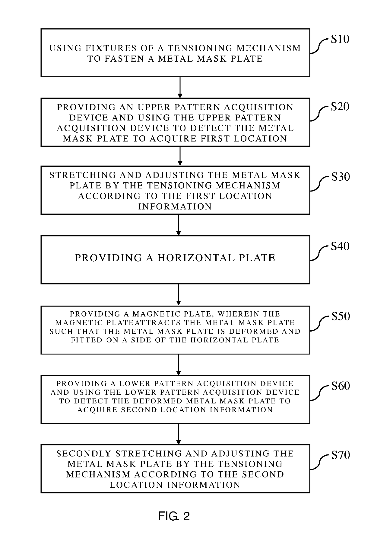
Thus, the technologic issue that the metal mask plate manufactured by the conventional screen stretcher device is deformed to result in location deviation of pixels defined on a surface of the glass substrate and further to cause defects of color mixing, lack of color and mura on the display panel is solved.

Method used


Image

  • Screen stretcher device
  • Screen stretcher device

Examples


Embodiment Construction

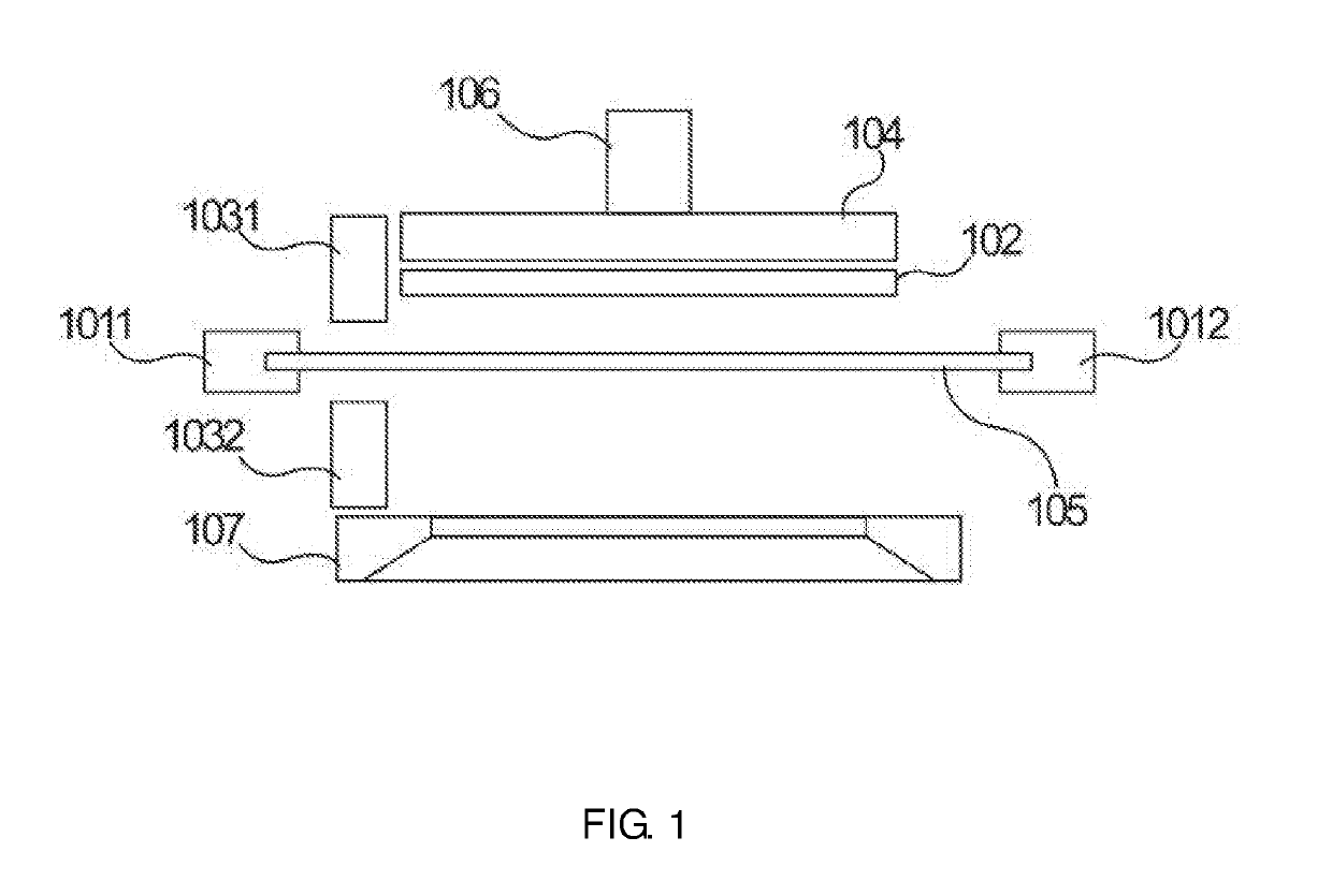
[0046]Each of the following embodiments is described with appending figures to illustrate specific embodiments of the present invention that are applicable. The terminologies of direction mentioned in the present invention, such as “upper”, “lower”, “front”, “rear”, “left”, “right”, “inner”, “outer”, “side surface” and etc., only refer to the directions of the appended figures. Therefore, the terminologies of direction are used for explanation and comprehension of the present invention, instead of limiting the present invention. In the figures, units with similar structures are marked with the same reference numerals.

[0047]The present invention aimed at the technical issue that the metal mask plate manufactured by the conventional screen stretcher device is deformed to result in location deviation of pixels defined on a surface of the glass substrate and further to cause defects of color mixing, lack of color and mura on the display panel. The present invention can solve the aboveme...


PUM

PropertyMeasurementUnit
surface roughnessaaaaaaaaaa
magnetic forceaaaaaaaaaa
magneticaaaaaaaaaa

Abstract

A screen stretcher device is provided and has a tensioning mechanism, a first fixture and a second fixture. The first fixture is securely disposed at one end of a metal mask plate, and the second fixture is securely disposed at the other end of the metal mask plate. A horizontal plate is disposed above the metal mask plate. A measuring mechanism is configured to acquire location information of a pattern on the metal mask plate. A magnetic mechanism is disposed above the horizontal plate, and is configured to attract the metal mask plate such that the metal mask plate is deformed.

Description

FIELD OF INVENTION[0001]The present invention relates to fields of display panel manufacture, especially to a screen stretcher device for manufacturing metal mask plates.BACKGROUND OF INVENTION[0002]Organic light-emitting diodes (OLEDs) have advantages such as self-light-emission, being all solid state, having high contrast, etc, and therefore have become the most potential new type of display devices recently. During manufacturing processes of the OLEDs, a precise metal mask for defining pixels (pixel regions) is required such that vaporized organic material may be deposited in the pixel regions. During a vapor deposition process, a metal mask plate tightly contacts a glass substrate by magnetic force. As such, quality of manufactured metal mask plate directly influences location precision of the vapor-deposited pixels.[0003]A conventional metal mask plate manufacturing process employs a screen stretcher, which welds an exposed and etched metal mask plate onto a metal frame to acqu...

Claims


Application Information

Patent Timeline
Patent Type & Authority Applications(United States)
IPC IPC(8): B21D25/04B21D26/14
CPCB21D25/04B21D26/14H01L51/56H01L51/0011C23C16/042C23C14/042H10K71/166B05C21/005H10K71/00
Inventor JIANG, LIANGLI, JINCHUAN
Owner SHENZHEN CHINA STAR OPTOELECTRONICS SEMICON DISPLAY TECH CO LTD
Why Eureka
Try Eureka