
Magnetic resonance fingerprinting method and apparatus

Inactive Publication Date: 2019-03-21
SIEMENS HEALTHCARE GMBH
View PDF6 Cites 3 Cited by
  • Summary
  • Abstract
  • Description
  • Claims
  • Application Information

AI Technical Summary

Benefits of technology

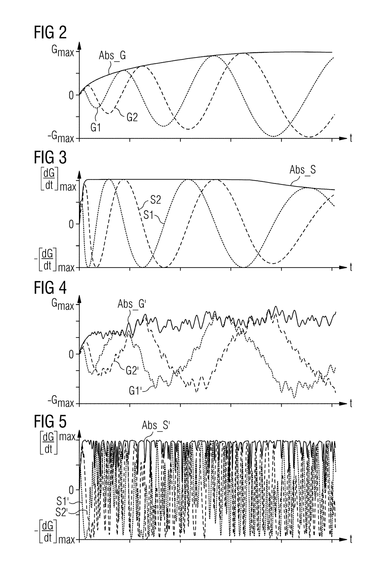
The invention aims to prevent errors and artifacts in magnetic resonance imaging (MRI) data obtained by MRF methods. This is achieved by fluctuating one or more parameters that determine the course of the k-space trajectory, which results in a less stringent and controlled measurement k-space trajectory. This results in incoherent noise in the recorded signals, reducing systematic errors, distortions, and artifacts in the final results. The fluctuation can be implemented by random variation of the parameters within predetermined limit values to ensure a sufficient degree of error.

Problems solved by technology

These coherences result in systematic errors and distorted MRF results, which manifest themselves as artifacts, sometimes referred to as foldover artifacts.

Method used


Image

  • Magnetic resonance fingerprinting method and apparatus
  • Magnetic resonance fingerprinting method and apparatus
  • Magnetic resonance fingerprinting method and apparatus

Examples


Embodiment Construction

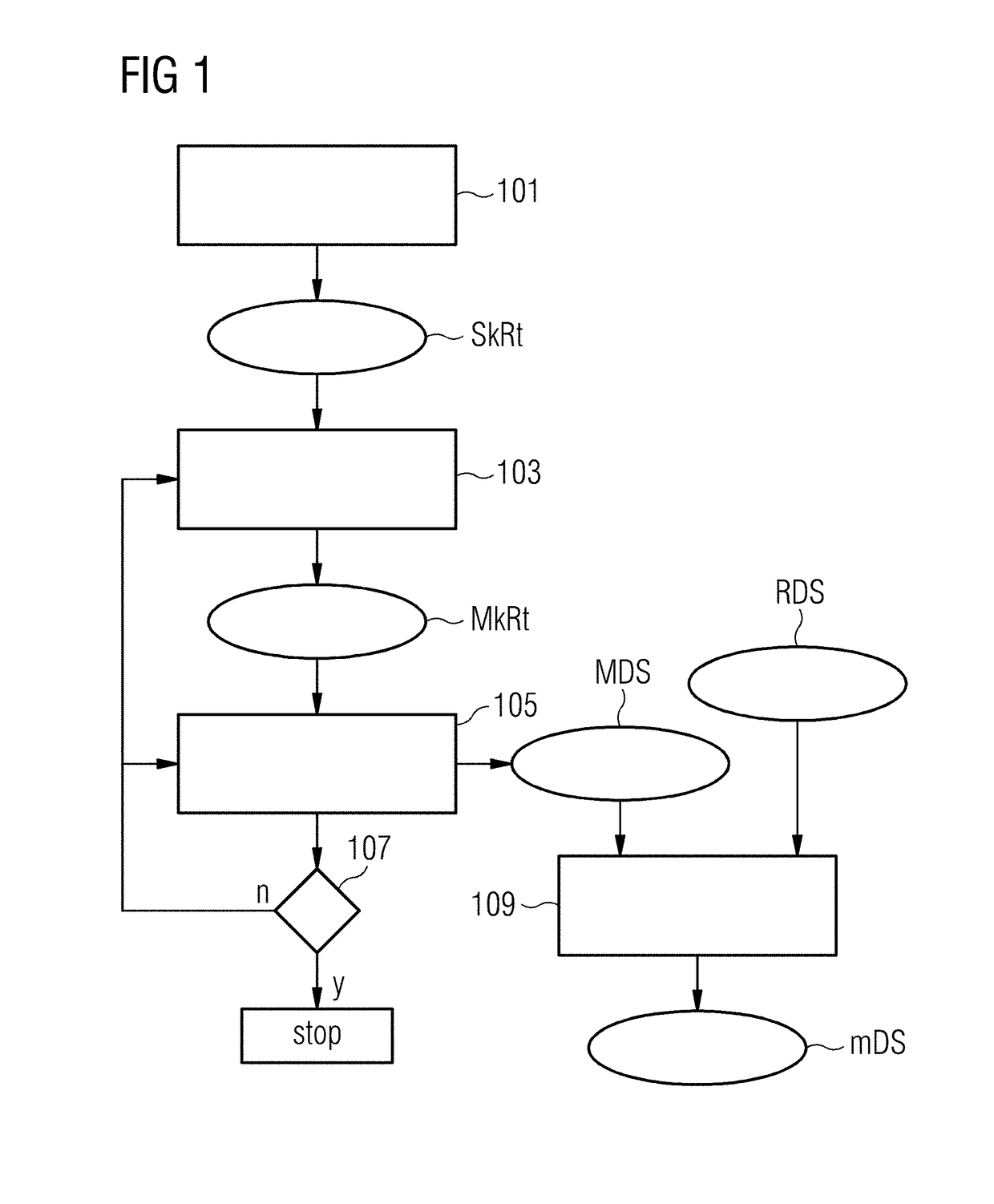
[0029]FIG. 1 is a flowchart of the method according to the invention for generating measurement data of an examination object by magnetic resonance fingerprinting.

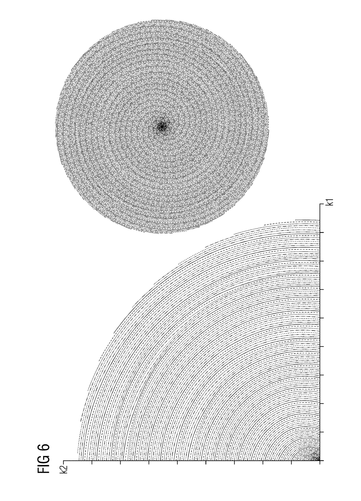
[0030]In the method, parameters are loaded into the control computer 9 of an MR apparatus 1 (shown in FIG. 8). The parameters describe a starting k-space trajectory SkRt, along which generated MR echo signals are to be entered into k-space as measurement data MDS (block 101). The loaded parameters contain information about RF pulses to be radiated, gradients to be switched, and readout times in their chronological order and relation to one another.

[0031]The starting k-space trajectory described by way of the parameters can be a Cartesian k-space trajectory or a radial or spiral k-space trajectory.

[0032]It is possible to record all the desired measurement data along only one k-space trajectory after only one excitation of echo signals (so-called “single-shot” method). Frequently the recording of measurement data takes place...


PUM


Abstract

In a method and apparatus for magnetic resonance (MR) fingerprinting, parameters that describe a starting k-space trajectory, along which measurement data are to be acquired in an MR fingerprinting sequence, are loaded into a computer, and at least one measurement k-space trajectory is created in the computer by fluctuating one of the parameters of the starting k-space trajectory. Measurement data are recorded along the measurement k-space trajectory, and the MR fingerprinting sequence is repeated with a different measurement trajectory in each repetition, produced by fluctuation of the at least one parameter of the starting k-space trajectory.

Description

BACKGROUND OF THE INVENTIONField of the Invention[0001]The present invention concerns magnetic resonance fingerprinting.Description of the Prior Art[0002]Magnetic resonance (MR) technology is a known technology with which images of the interior of an examination object can be generated. In simple terms, the examination object is positioned in a magnetic resonance scanner in a strong static, homogenous basic magnetic field, also referred to as a B0 field, with field strengths of 0.2 tesla to 7 tesla or more, such that nuclear spins in the object orient themselves along the basic magnetic field. To trigger magnetic resonance signals, radio-frequency excitation pulses (RF pulses) are radiated into the examination object, with rapidly switched magnetic gradient fields being superimposed on the basic magnetic field for spatially encoding the triggered MR signals. The recorded signals are digitized and stored as complex numerical values in a memory as so-called k-space data, such as in a ...

Claims


Application Information

Patent Timeline
IPC IPC(8): G01R33/48G01R33/54G01R33/36G01R33/385
CPCG01R33/4818G01R33/543G01R33/3607G01R33/385G01R33/4824G01R33/4828G01R33/50G01R33/5602
Inventor PFEUFFER, JOSEF
Owner SIEMENS HEALTHCARE GMBH
Learn More