Thermal panel

a technology panels, applied in the field of thermal insulation systems, can solve the problems of affecting the performance and affecting the quality of acoustic honeycomb panels

Active Publication Date: 2019-03-21
HEXCEL
View PDF8 Cites 1 Cited by
  • Summary
  • Abstract
  • Description
  • Claims
  • Application Information

AI Technical Summary

Benefits of technology

The present invention pertains to a thermal panel that can protect sensitive structures in jet engines from heat. The panel is made of a strong corrugated core and insulating material, which provides adequate protection without compromising the thermal insulation. The structurally strong composite corrugated core acts as a support for the insulating materials while minimizing the number of potential thermally conductive pathways. This unique combination of properties is difficult to achieve with other structural designs. Overall, the invention provides a better thermal protection solution for thermally sensitive structures in jet engines.

Problems solved by technology

This is a particular problem for composite sound damping structures, such as acoustic honeycomb panels, which are made from composite materials that utilize matrix resins which have maximum operating temperatures on the order of 350° F. to 500° F. The material used to make the acoustic septa that are typically present in such acoustic honeycomb panels may also be damaged when exposed directly to the heat generated by the hot section.
Although thermal blankets provide adequate thermal insulation, they do present a number of design challenges.
The high vibration environment of a jet engine causes the fiberglass stitching to degrade over time.
As a result, the quilted compartments of insulation become undone so that the filler may move within the blanket causing concentration of filler in some areas and leaving other areas unprotected.
Accordingly, the service life of a typical thermal blanket is limited and it must be replaced at specified time intervals.
This removal and reinstallation process is time consuming and many times results in the heat blanket being damaged due to the non-structural nature of the blanket.
Repairing and / or replacing a damaged thermal blanket can involve significant added time and costs.
However, the insulating coatings must be scrapped and peeled off in order to inspect the underlying structure.
This is a time consuming process that also destroys the coating.
Application of a new silicone coating is a time consuming process that includes the additional cost of the new high temperature silicone coating material.
These design goals are made particularly difficult due to the unique operating environment of a jet engine and the need to provide lightweight insulating structures that are structurally strong and which can also be formed into complex curved shapes.

Method used


Image

  • Thermal panel
  • Thermal panel
  • Thermal panel

Examples


Embodiment Construction

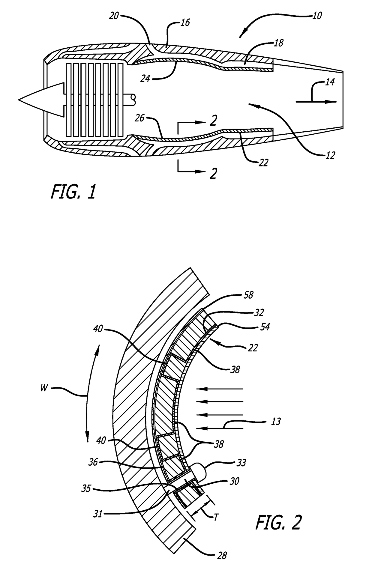
[0021]The thermal panels of the present invention may be used for insulating a wide variety of heat sensitive structures from a wide variety of heat sources. The thermal panels are well-suited for use in protecting the heat sensitive portions of a jet engine from the heat generated in the combustion (hot) section of the engine. Accordingly, the thermal panels are intended to be used where the heat source has a temperature of from 500° F. to 1000° F. with temperatures of between 600° F. to 750° F. being typical for current jet engines. The thermal protection provided by the thermal panel should be such that the structure or body being thermally protected is exposed to temperatures on the order of 350° F. to 500° F.

[0022]The following detailed description is limited to exemplary embodiments of thermal panels that are located within a jet engine. The thermal panels are intended to be used as a replacement for the thermal blankets that are presently commonly used in jet engines to therm...


PUM

PropertyMeasurementUnit
Temperatureaaaaaaaaaa
Widthaaaaaaaaaa

Abstract

A thermal paid having a high temperature side located nearest a source of heat and a low temperature side. The thermal panel includes a corrugated composite material core having hot side ridges and cold side ridges. A hot side skin is attached to the hot side ridges to form a plurality of first cells. A cold side skin is attached to the cold side ridges to form a plurality of second cells. The first cells and second cells are substantially filled with an insulating material that has a thermal conductivity which is lower than the thermal conductivity of the composite material.

Description

BACKGROUND OF THE INVENTION1. Field of the Invention[0001]The present invention relates generally to thermal insulation systems that are used to protect thermally sensitive structures from damage that might be caused by heat exposure. More particularly, the invention is directed to jet engines and the thermal insulation systems that protect lower temperature structures or bodies in the jet engine from heat generated in the combustion section.2. Description of Related Art[0002]Jet engines include a combustion or hot section that is located centrally within the engine. The hot section produces large amounts of hot combustion gases. The hot section is surrounded by an annular passageway through which air flows at much colder temperatures. The hot sections of present day jet engines typically operate at temperatures on the order of 500° F. to 750° F. with temperatures as high as 900° F. being possible in order to produce lower emissions and to achieve greater fuel economy.[0003]Thermall...

Claims


Application Information

Patent Timeline
IPC IPC(8): F23R3/00F23R3/60B32B3/28B32B18/00
CPCF23R3/002F23R3/007F23R3/60B32B3/28B32B18/00F05D2260/231F05D2300/5024F05D2300/603B32B2307/304B32B7/12B32B9/005B32B2607/00F02K1/825F02C7/25F02K1/822F02C7/24
Inventor HAILE, MERIDAYLE, EARLDAILEY, WHITNEY
Owner HEXCEL
Why Eureka
Try Eureka