Air purifier and air purification method

Active Publication Date: 2019-03-14
KONINKLJIJKE PHILIPS NV
View PDF0 Cites 0 Cited by
  • Summary
  • Abstract
  • Description
  • Claims
  • Application Information

AI Technical Summary

Benefits of technology

The patent describes a way to use a concentration sensor to determine information about the performance of a gas filter, such as how long it has been used or how well it is doing. This sensor is low cost and can be easily installed. It measures the difference in pollutant concentration before and after the filter, allowing for real-time monitoring. The system does not require multiple sensors or measurements at different modes of operation. The sensor can be used in existing air purifiers and can provide a real-time alert of filter failure, ensuring clean air for consumers. A reference electrode is used to make absolute concentration levels measurements, improving the reliability of the measurements. Overall, this technology provides a cost-effective and accurate way to monitor gas filter performance.

Problems solved by technology

If the pressure drop increases beyond a pre-set threshold, the filter has been overloaded with particles surpassing its capacity, which means the filter has reached the end of its useful lifetime.
However, for detection of a gas filter lifetime, there is no such simple and reliable solution, which can satisfy the requirement of continuous in-situ monitoring at a low cost.
Alternatively, expensive professional instruments have to be leveraged twice to measure the gaseous pollutant level before and after the gas filter respectively.
Employment of two independent sensors at both sides of the filter to check the pollutant concentration difference may not be reliable due to large sensor-to-sensor variation.
This is an inaccurate estimation method and it does not reflect real filter conditions.
It may either be risky to expose consumers to air pollution by running an ineffective filter, or not ecologically friendly due to replacement of an unexhausted filter.
Reliable methods to detect the filter lifetime for particle filters exist but unfortunately currently there are no suitable methods for gas filters.

Method used


Image

  • Air purifier and air purification method
  • Air purifier and air purification method
  • Air purifier and air purification method

Examples


Embodiment Construction

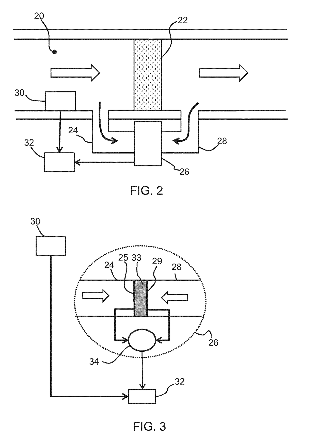
[0047]The invention provides an air purifier comprising a gas filter between an upstream air flow and a downstream air flow and a concentration sensor comprising a first electrode and a second electrode, the first electrode being exposed to the upstream air flow and the second electrode exposed to the downstream air flow, the concentration sensor providing an output signal based on the difference in concentrations of a target gas at the first and second electrodes. The output signal is processed to determine information relating to the condition of the gas filter.

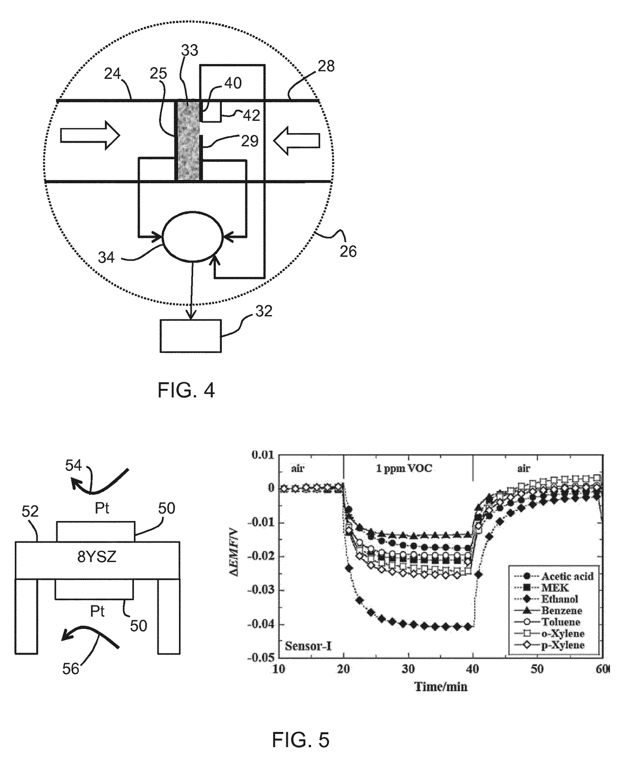
[0048]The invention for example makes use of a sensor of a type which is known for use in a concentration cell, for example of the type used as an oxygen sensor for controlling the air-to-fuel ratio in automobiles.

[0049]An example of this type of sensor is shown in FIG. 1. The sensor comprises a probe 1 which extends into an exhaust gas flow 10. The probe comprises a stabilized zirconia (ZrO2) electrolyte 12 surrounded by P...


PUM


Abstract

An air purifier comprise a gas filter between an upstream air flow and a downstream air flow and a concentration sensor comprising a first electrode and a second electrode, the first electrode being exposed to the upstream air flow and the second electrode exposed to the downstream air flow, the concentration sensor providing an output signal based on the difference in concentrations of a target gas at the first and second electrodes. The output signal is processed to determine information relating to the con- dition of the gas filter.

Description

FIELD OF THE INVENTION[0001]This invention relates to air purifiers, and in particular relates to indication of the filter lifetime in such air purifiers.BACKGROUND OF THE INVENTION[0002]Particle filters and gas filters are usually incorporated into an air purifier for filtering out airborne pollutants.[0003]The lifetime of particle filters can be derived by checking the pressure drop caused. The pressure drop across the particle filter can be easily monitored in-situ and in real time using a differential pressure gauge. If the pressure drop increases beyond a pre-set threshold, the filter has been overloaded with particles surpassing its capacity, which means the filter has reached the end of its useful lifetime. This way of detecting the particle filter lifetime is in consistent with professional detection methods in laboratory and industry.[0004]However, for detection of a gas filter lifetime, there is no such simple and reliable solution, which can satisfy the requirement of con...

Claims


Application Information

Patent Timeline
IPC IPC(8): F24F11/32F24F3/16F24F8/108F24F8/158
CPCF24F11/32F24F3/1603F24F2003/1614F24F2110/64G01N27/409F24F11/30F24F2110/50G01N27/66F24F8/108Y02B30/70F24F11/39F24F8/158Y02A50/20
Inventor XUE, RUIFENGKE, RUIZHU, SHANCHEN, SHUANG
Owner KONINKLJIJKE PHILIPS NV
Why Eureka
Try Eureka