Control system for a compressor with speed-based subsystem, synthesis plant and control method

a control system and compressor technology, applied in the direction of fluid pressure control, process and machine control, instruments, etc., can solve problems such as adversely affecting the composition of certain operating conditions

Inactive Publication Date: 2019-03-14
NUOVO PIGNONE TECH SRL
View PDF0 Cites 1 Cited by
  • Summary
  • Abstract
  • Description
  • Claims
  • Application Information

AI Technical Summary

Problems solved by technology

Although the plant is designed so to maintain the composition of the gas mixture constant, one or more of these units may adversely affect the composition in certain operating conditions.

Method used


Image

  • Control system for a compressor with speed-based subsystem, synthesis plant and control method
  • Control system for a compressor with speed-based subsystem, synthesis plant and control method
  • Control system for a compressor with speed-based subsystem, synthesis plant and control method

Examples


Embodiment Construction

[0022]The following description of exemplary embodiments refers to the accompanying drawings.

[0023]The following description does not limit embodiments of the invention. Instead, the scope of embodiments of the invention is defined by the appended claims.

[0024]Reference throughout the specification to “one embodiment” or “an embodiment” means that a particular feature, structure, or characteristic described in connection with an embodiment is included in at least one embodiment of the subject matter disclosed. Thus, the appearance of the phrases “in one embodiment” or “in an embodiment” in various places throughout the specification is not necessarily referring to the same embodiment. Further, the particular features, structures or characteristics may be combined in any suitable manner in one or more embodiments.

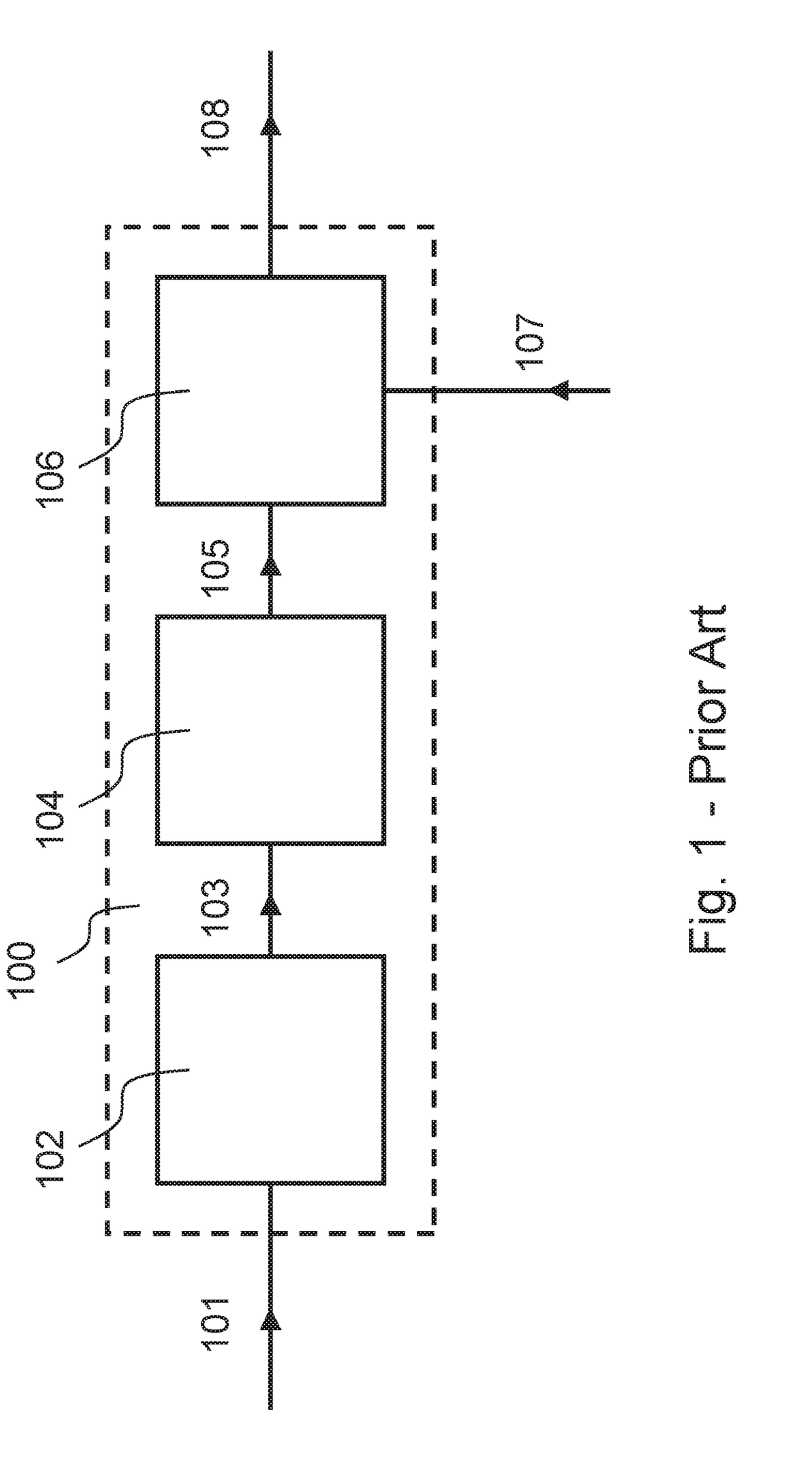
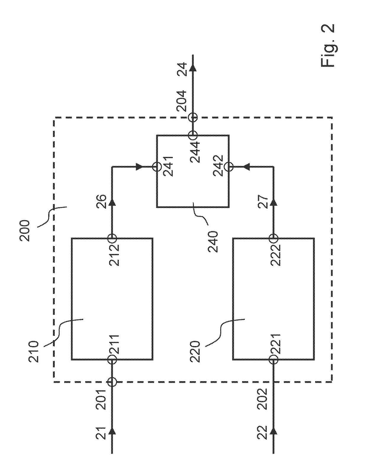
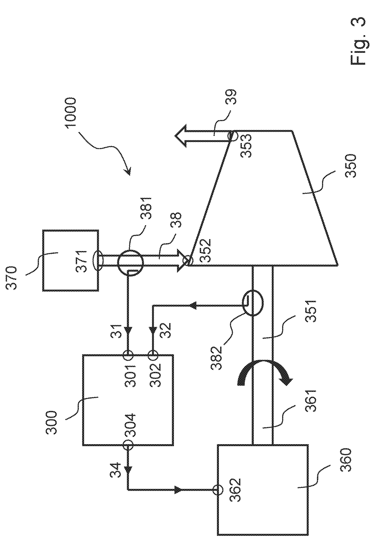
[0025]In the following, embodiments of the subject matter disclosed herein will be described through block diagrams made of blocks connected by lines entering into and exiti...


PUM


Abstract

Control system arranged for a rotary compressor driven by a rotary engine, and includes: a first control subsystem, a second control subsystem and a selector; the first control subsystem is arranged to provide a first control signal as a function of the performance of the compressor; the second control subsystem is arranged to provide a second control signal as a function of the speed of the compressor; the selector is arranged to select the first control signal or the second control signal as a third control signal to be provided to a power control input of the engine.

Description

FIELD OF THE INVENTION[0001]Embodiments of the subject matter disclosed herein correspond to control systems for a rotary compressor driven by a rotary engine, synthesis plants and control methods.BACKGROUND OF THE INVENTION[0002]Trains comprising a compressor driven by an engine are quite common, in particular in the field of “Oil & Gas”.[0003]A typical control system for such trains, such as system 100 shown in annexed FIG. 1, determines (block 102) a load demand 103 based on a (detected) suction pressure 101 of the compressor, then determines (block 104) a speed setpoint 105 based on the previously-determined load demand 103, and finally determines (block 106) a control signal 108 based on the previously-determined speed setpoint 105 and a (detected) rotation speed 107 of the compressor; the so-determined control signal 108 is fed to a control input of the engine. A control system of this type is disclosed, for example, in U.S. Pat. No. 3,979,655.[0004]Such typical control system...

Claims


Application Information

Patent Timeline
Patent Type & Authority Applications(United States)
IPC IPC(8): F04D27/00G05B6/02F04D27/02F04D25/04
CPCF04D27/004G05B6/02F04D27/02F04D27/001F04D25/04F04D27/0207F05D2270/706F05D2270/303F05D2270/3011F05D2270/3013F05D2270/304F04D27/0261Y02B30/70F02C9/28G05D13/60G05D16/2066
Inventor CALOSI, MIRCOSIGNORINI, ANNAMARIAPASQUOTTI, MAURAMOSCATELLI, PASQUALE GIANLUCARIZZELLI, MARCOPELELLA, MARCO
Owner NUOVO PIGNONE TECH SRL
Why Eureka
Try Eureka