
3D printed osteogenesis scaffold

a 3d printing and osteogenesis technology, applied in the field of 3d printing osteogenesis scaffolds, can solve the problems of bone pressure necrosis, inconsistent mechanical strength of patients' own autografts, and implants based on bone material

Active Publication Date: 2019-03-14
MCA GRP LLC
View PDF4 Cites 0 Cited by
  • Summary
  • Abstract
  • Description
  • Claims
  • Application Information

AI Technical Summary

Benefits of technology

The patent text explains how using an isotropic implant can cause stress shielding, meaning the implant makes the bone weaker in one direction. To address this issue, an anisotropic porous scaffold support structure is used, which matches the anisotropy of the nearby native bone. The technical effect of this is that it helps the implant to reduce or avoid stress shielding, making it stronger and more secure in the long term.

Problems solved by technology

Unfortunately, these implant materials have a modulus which is much higher than that of bone and there is clinical evidence of implant subsidence and movement which is believed to be attributable to mechanical incompatibility between natural bone and the implant material.
Also bone pressure necrosis does occur as a result of the presence of these metal implants.
Implants based on bone material from a donor (allograft) or from the patient itself (autograft) do have an inconsistent mechanical strength and show subsidence over time.
The inconsistent properties of these implants make them generally unpredictable, challenging to reliably machine and especially prone to migration and explusion due to the difficulty of consistently machining teeth into the upper and lower implant contact surfaces.
Although titanium alloy cages give good fusion rates, their modulus is significantly dissimilar to human bone.
The stress transfer between an implant device and a bone is not homogeneous when Young's moduli of the implant device and the bone are different.
This results in stress shielding.
In such conditions, bone atrophy occurs and leads to the loosening of at the implant bone interface and eventually lead to failure.

Method used


Image

  • 3D printed osteogenesis scaffold
  • 3D printed osteogenesis scaffold
  • 3D printed osteogenesis scaffold

Examples


Embodiment Construction

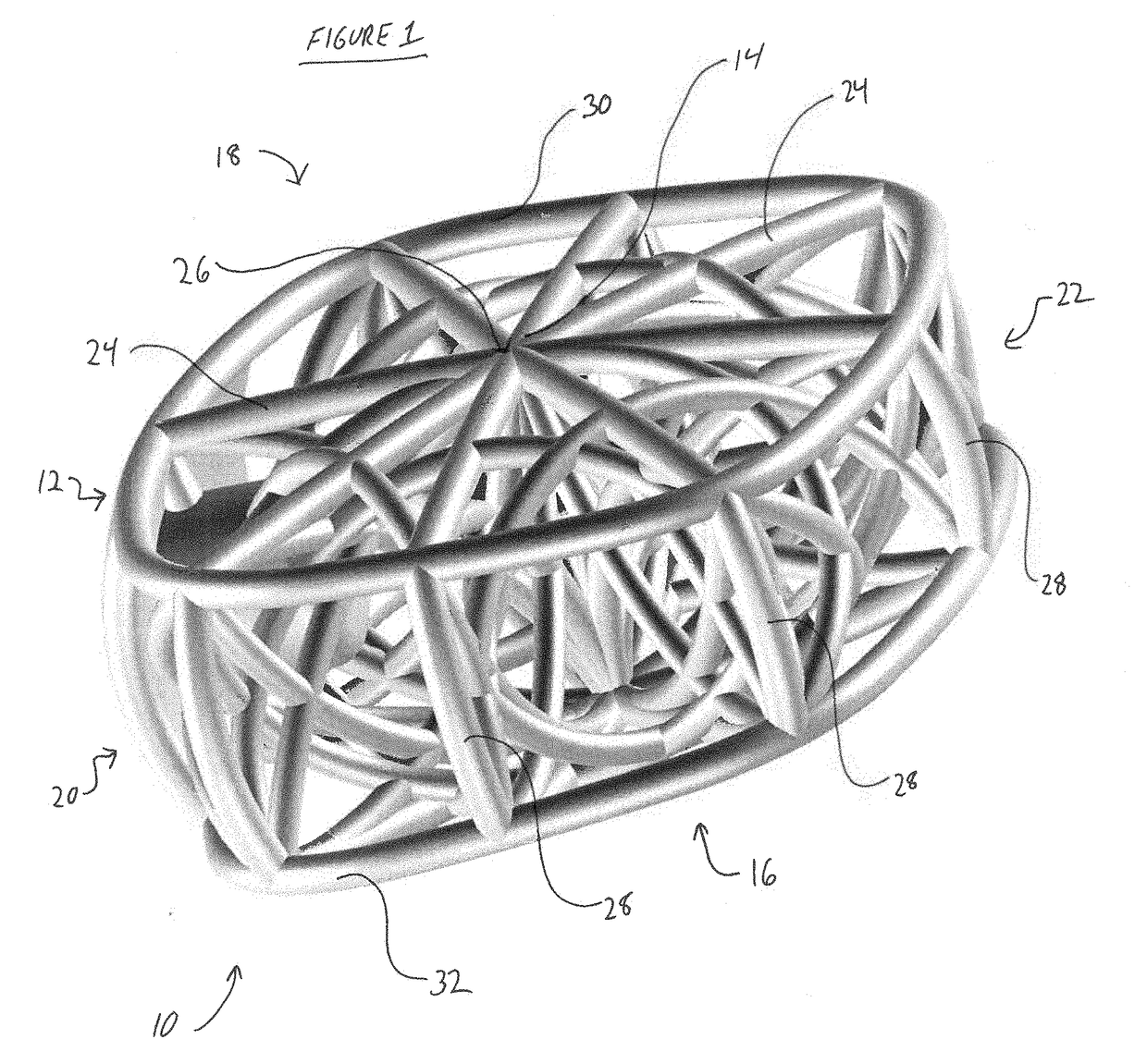
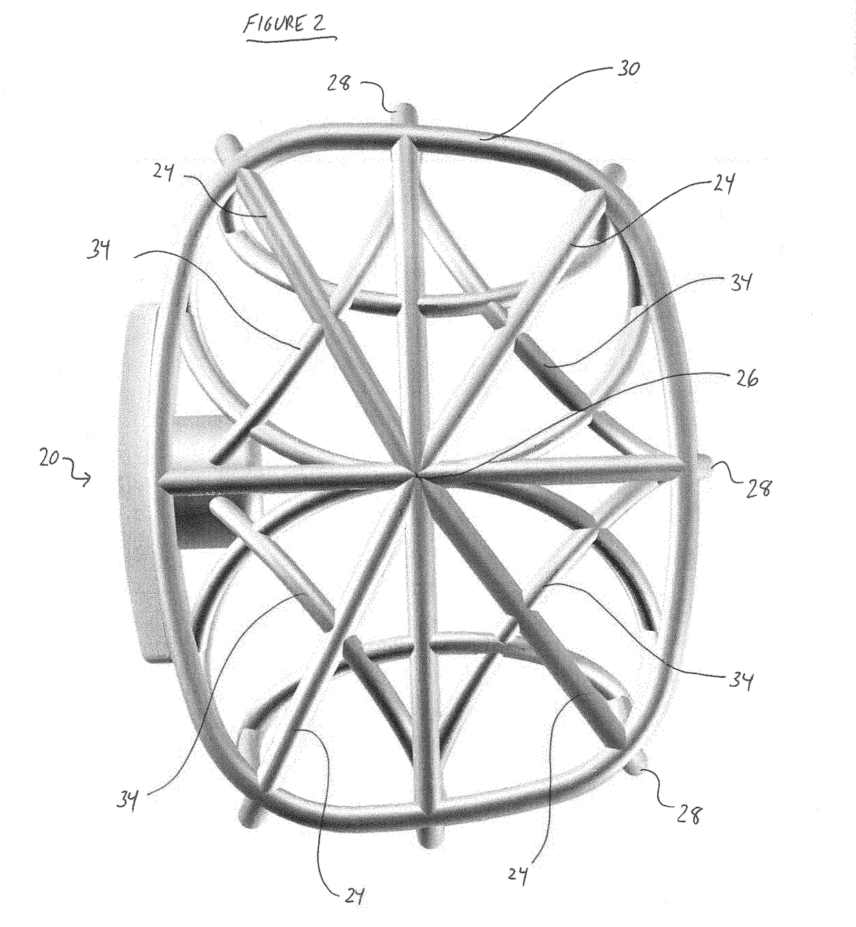
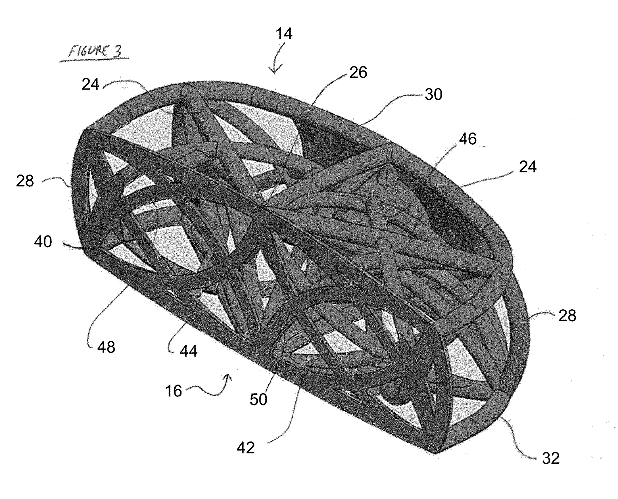
[0013]The present invention addresses the problem by providing implants such as intermedullary nails or spinal fusion cages that have a functional modulus of elasticity that is substantially the same as the modulus of elasticity of the native bone at the implant site. For example, implants can be provided having a functional modulus of elasticity of between about 5 GPa and about 75 GPa, typically between about 10 GPa and about 50 GPa and in some implementations between about 10 and about 30 GPa. Functional modulus means the effective modulus of the final implant, which will be the result of both the modulus of the material of the implant as well as the result of the arcuate strut architecture of the implant, as will be described below.

[0014]In addition, human or animal tissue is generally not structurally isotropic. For example, cancellous bone includes trabeculae, also referred to as spicules, defining a plurality of open spaces. The trabeculae and open spaces are generally oriente...


PUM

PropertyMeasurementUnit
Young's modulusaaaaaaaaaa
compressive strengthaaaaaaaaaa

Abstract

Osteogenesis scaffold such as for spinal fusion or an intermedullary nail includes a number of arcuate struts. The scaffold may have a functional modulus of elasticity that is a result of the modulus of the material of the struts together with the architecture of the struts, and may be within the range of 5 GPa and 75 GPa. An anisotropy of a physical property such as stiffness, compressive strength or elastic modulus corresponds to the same physical property of native bone in the vicinity of the intended implantation site.

Description

CROSS-REFERENCE TO RELATED APPLICATIONS[0001]This application is a continuation application of U.S. application Ser. No. 15 / 299,347, filed Oct. 20, 2016, which claims the priority benefit under 35 U.S.C. §119(e) of U.S. Provisional Application No. 62 / 244,374, filed Oct. 21, 2015, the entirety of which is hereby incorporated by reference herein.BACKGROUND OF THE INVENTION[0002]Spondylosyndesis, or spinal fusion, is a surgical technique used to combine two or more vertebrae into a single, rigid working unit. This is typically achieved by introducing a supplementary bone tissue, such as an autograft or allograft, into the intervertebral space between two target vertebrae, at the location that is typically occupied by an intervertebral disc. The supplementary bone tissue is then used in conjunction with the patient's natural osteoblastic processes in order to grow bone or osseous tissue between the two or more target vertebrae, which acts to fuse them together into the desired rigid uni...

Claims


Application Information

Patent Timeline
Patent Type & Authority Applications(United States)
IPC IPC(8): A61F2/44A61B17/72A61B17/00A61F2/30
CPCA61B2017/00862A61F2002/30069A61F2002/3008A61B17/72A61F2002/4475A61F2/4465A61F2002/30062A61F2/4455A61F2002/30187A61F2002/30571A61F2002/30593A61F2002/30985A61F2002/4495
Inventor AFZAL, THOMAS
Owner MCA GRP LLC
Learn More