Dual-notch antenna and antenna array thereof

Active Publication Date: 2019-03-07
CUBTEK INC
View PDF5 Cites 7 Cited by
  • Summary
  • Abstract
  • Description
  • Claims
  • Application Information

AI Technical Summary

Benefits of technology

The present invention is about a dual-notch antenna and its array that can improve the performance of array antennas. It solves issues of signal reflection and optimizes the antenna radiation pattern. The design includes concavely placed notches on the sides of each radiation member, which allows for optimal impedance match and increases the effective frequency of the antenna. By arranging the radiation members in series and forming a string array, external frequency bandwidth is effectively increased, leading to improved performance.

Problems solved by technology

Because a vehicle bumper is usually provided with a shock absorbing Styrofoam or fiberglass therein, the internally available space is limited.
As a result, the radar signal is easily attenuated, causing a designing difficulty of the antenna array.
Increasing the antenna performance and raising the antenna gain at a high frequency is difficult.
In addition, the available space limitation is to be considered.
Therefore, the difficulty of the antenna designing is increased.
However, as shown by the reflection coefficient frequency response diagram, the effective bandwidth of the antenna at a frequency about 24 GHz is not optimal, failing to achieve a preferably impedance match for avoiding the signal reflection.
However, such structure is not suitable for antenna array.

Method used


Image

  • Dual-notch antenna and antenna array thereof
  • Dual-notch antenna and antenna array thereof
  • Dual-notch antenna and antenna array thereof

Examples


Embodiment Construction

[0022]The aforementioned and further advantages and features of the present invention will be understood by reference to the description of the preferred embodiment in conjunction with the accompanying drawings where the components are illustrated based on a proportion for explanation but not subject to the actual component proportion.

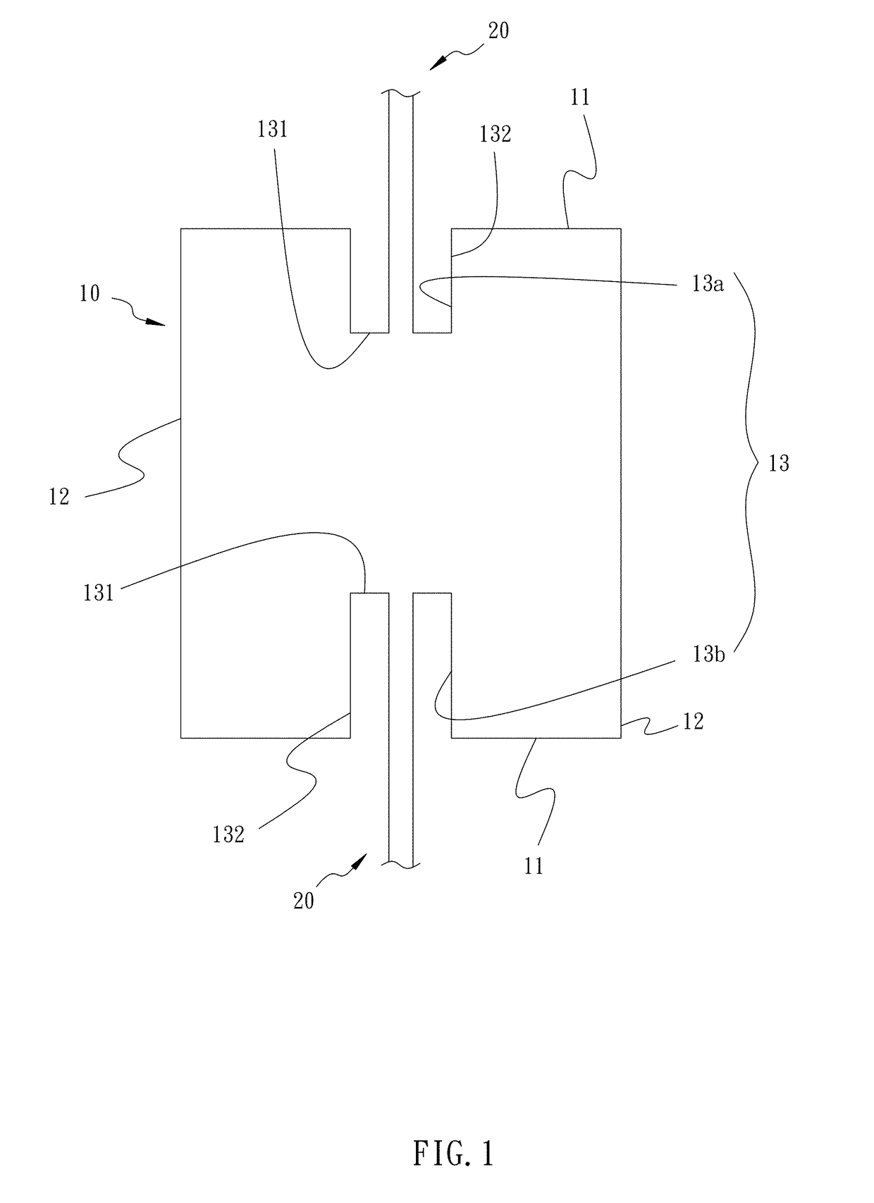
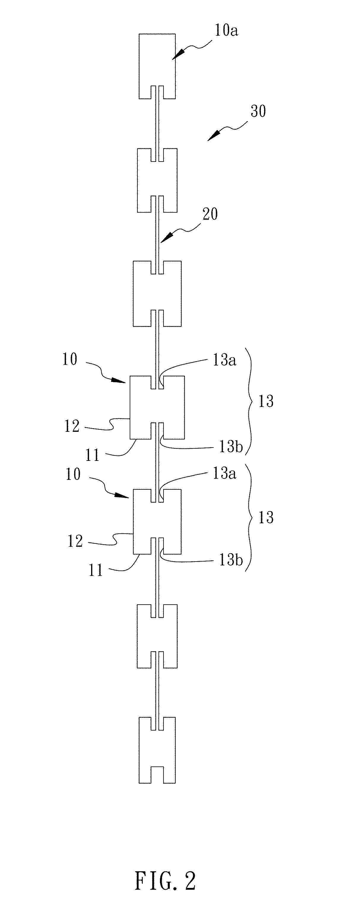
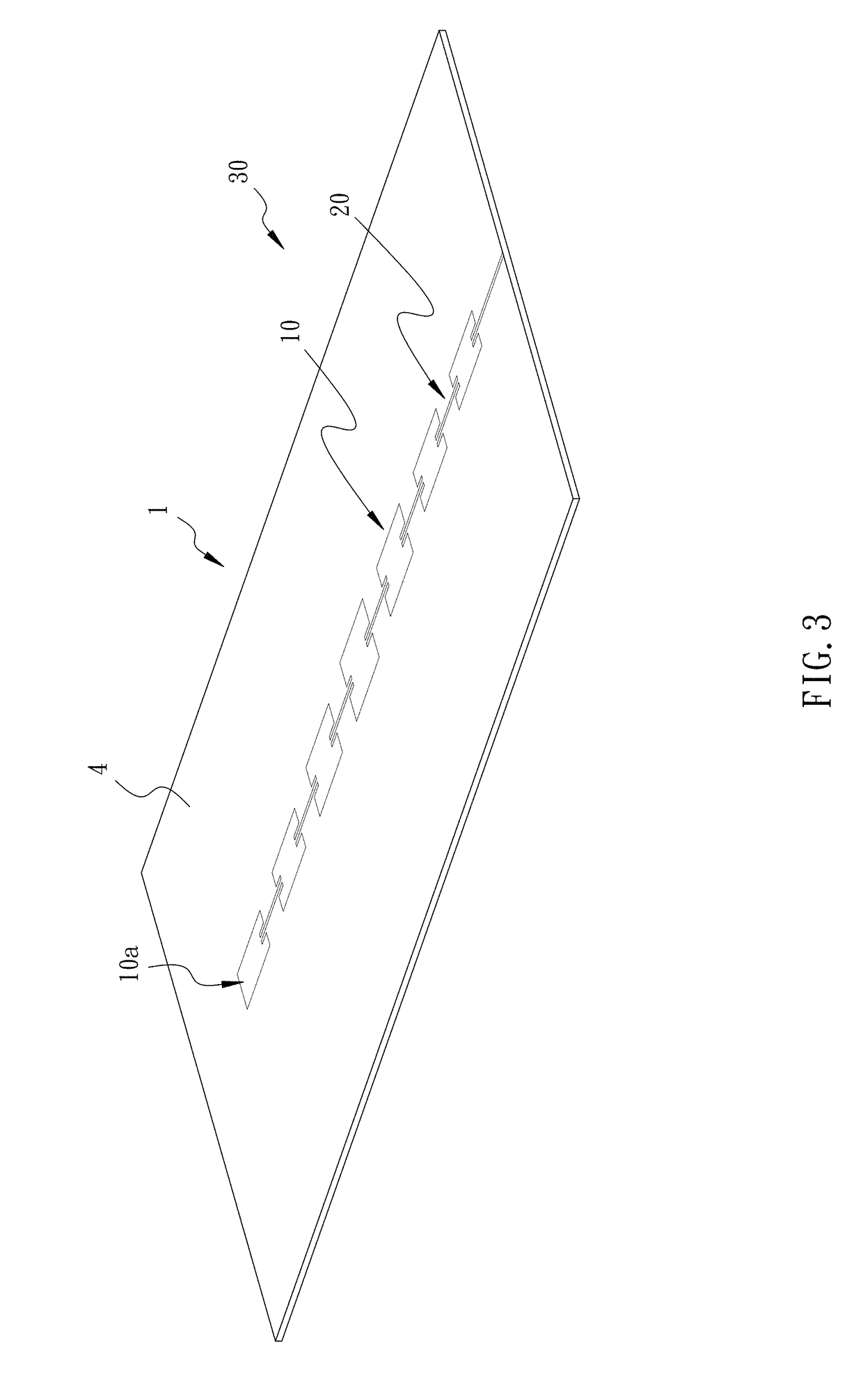
[0023]Referring to FIG. 1, FIG. 5, FIG. 6, and FIG. 7, an embodiment of the present invention provides a dual-notch antenna. In an embodiment, the dual-notch antenna refers to a microstrip antenna. The dual-notch antenna is disposed on a circuit board 1, comprising a substrate layer 2 and a grounding layer 3 that are stacked. The substrate layer 2 is provided with a first face 4 and a second face 5 disposed in opposite to the first face 4. The dual-notch antenna is disposed on the first face 4, and the grounding layer 3 is disposed on the second face 5. The dual-notch antenna comprises a radiation member 10 and two microstrip lines 20.

[0024]The radiati...


PUM


Abstract

A dual-notch antenna includes a radiation member and two microstrip lines. The radiation member is formed in a rectangular shape, with two first lateral sides disposed in opposite, and two second lateral sides disposed on two ends of the two first sides, respectively. The middle section of each first lateral side is concavely provided with a notch. Each notch has a feeding side and two cove sides, wherein the feeding side is disposed in parallel to the first lateral sides. The two cove sides are connected with two ends of the feeding side. Each microstrip line has one end thereof electrically connected with the feeding side of the corresponding notch, respectively.

Description

BACKGROUND OF THE INVENTION1. Field of the Invention[0001]The present invention relates to antenna and antenna array, and more particularly, to a dual notch antenna and antenna array thereof efficiently increasing the impedance bandwidth.2. Description of the Related Art[0002]Typically, most of vehicle radar system applies a microstrip antenna array, with a wireless signal transceiver of the vehicle radar system disposed inside a vehicle bumper or a fan guard. The vehicle radar system transmits and receives millimeter-wave wireless signal for carrying out application such as distance detection or information exchange. Because a vehicle bumper is usually provided with a shock absorbing Styrofoam or fiberglass therein, the internally available space is limited. As a result, the radar signal is easily attenuated, causing a designing difficulty of the antenna array.[0003]Also, typical vehicle radar system operates in a frequency band between 24 GHz to 77 GHz. Increasing the antenna perf...

Claims


Application Information

Patent Timeline
IPC IPC(8): H01Q21/06H01Q1/32
CPCH01Q21/065H01Q1/3233H01Q21/0075
Inventor YU, SAN-CHUANCHUNG, SHYH-JONGTSAI, CHING-HANWANG, BO-YI
Owner CUBTEK INC
Why Eureka
Try Eureka