
Method(s) and Apparatus For Treating Waste

a technology of waste and treatment method, applied in lighting and heating apparatus, water/sludge/sewage treatment, drying, etc., can solve the problems of large plants, high energy requirements, complex and expensive disposal processes,

Inactive Publication Date: 2019-03-07
ENERGY RECOVERY SYST
View PDF0 Cites 17 Cited by
  • Summary
  • Abstract
  • Description
  • Claims
  • Application Information

AI Technical Summary

Benefits of technology

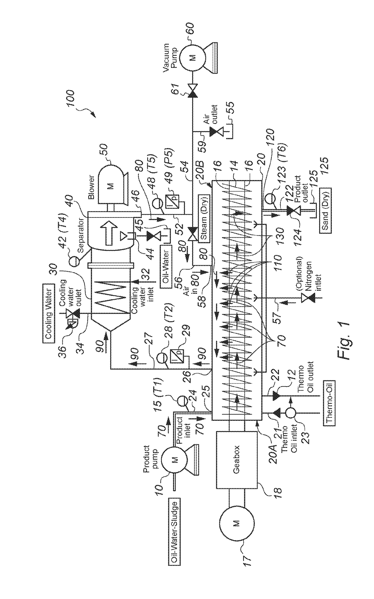
The treatment chamber is designed to have a vacuum, and there is a vacuum pump to create the vacuum. The preferred vacuum is between 0.1 and 0.5 bar, with a bit more allowable under certain conditions. The vacuum needs to be maintained consistent with little change over time. This patent is important for creating the optimal conditions for a vacuum treatment process.

Problems solved by technology

Existing disposal processes are complicated and expensive, as hydrocarbon content must be reduced to low value e.g. below 1% by mass before the waste can be landfilled.
Various onshore treatment technologies exist, but are characterised by large plants, and high energy requirements.
This process is not particularly efficient or effective and may suffer from low throughput volumes.
This document does not address the problem of thermal processing of liquids such as slurries.
This process and apparatus is unsuitable for the processing of liquids such as slurries.
Laterally placed perforations in the kiln body allow vapour to escape rendering the process of liquids, such as slurries, problematic.
Several of the above documents provide for use of chemicals, or a chemical change in the constituents, or use of very high temperatures, or open flames, thus rendering these unsuitable for use in high risk environments (e.g. on oil and gas installations offshore or onshore).

Method used


Image

  • Method(s) and Apparatus For Treating Waste
  • Method(s) and Apparatus For Treating Waste
  • Method(s) and Apparatus For Treating Waste

Examples


Embodiment Construction

[0079]A slurry is a mixture of insoluble solids, typically in particulate form, in one or more liquids, examples include cement slurry, bentonite slurry, clay slurry, coal slurry. Other examples of slurries may include two or more immiscible liquids such as one or more oil(s) and water as well as insoluble solid particles. These are particularly difficult to separate into component parts for disposal.

[0080]In fish waste processing macerated salmon may comprise around 28% oil in a slurry of solids, oil(s), and water. The fish oil will evaporate out at around 90° C.

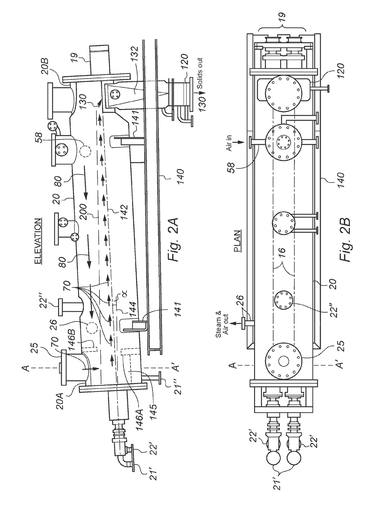
[0081]Treatment of large volumes of slops (e.g. slurries) in oil and gas, and fish processing industries is costly and an environmentally challenging task. The present invention provides method(s) an apparatus for the treatment of oily contaminated drilling slops that can be used at on shore treatment facilities or offshore (rig-based) locations. The apparatus is (relatively) compact and mobile, is easy to operate, has lowe...


PUM


Abstract

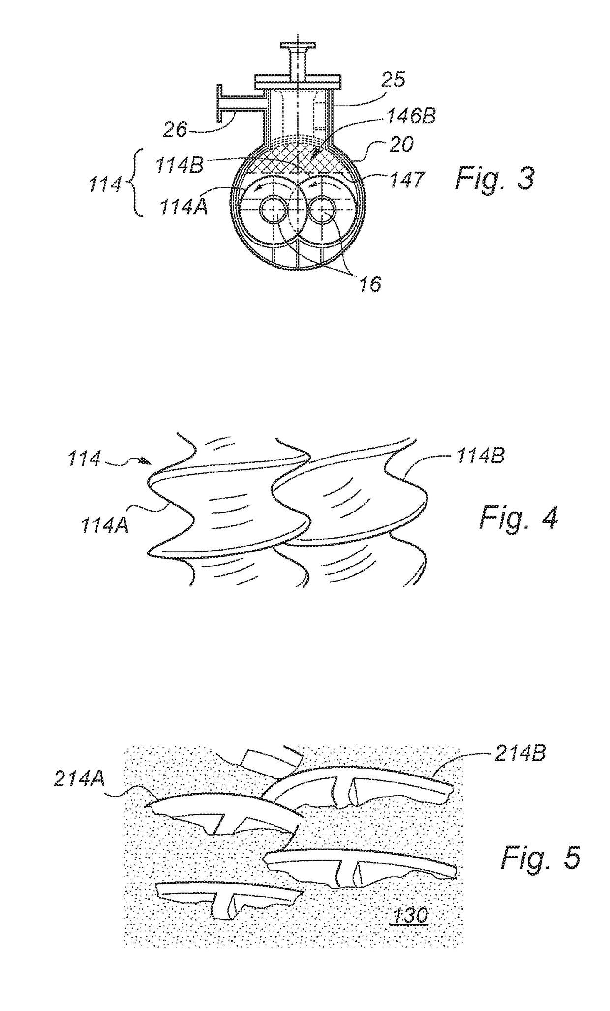
The present invention relates to method(s), apparatus and use(s) of apparatus for treating materials such as waste products and by-products of industrial processes e.g. slurries comprising solids and liquids, or, more particularly, slurries comprising solids, oil(s), and water. The invention further relates to method(s), apparatus and use(s) for treating slurry, the apparatus comprising a treatment chamber having a first end configured to receive slurry to be treated and a second end configured to allow egress of solids; at least one heated material conveyor configured to draw material comprising slurry and / or solids through the chamber in a direction from the first end towards the second end; the at least one heated material conveyor being further configured to heat and mix material comprising slurry and / or solids as these are drawn along; a condenser configured to receive vapours from the chamber and condense the vapours into liquid form.

Description

CROSS-REFERENCE TO RELATED APPLICATION(S)[0001]This application is the U.S. National Phase application of PCT application number PCT / GB2017 / 050600 having a PCT filing date of Mar. 7, 2017, which claims priority of United Kingdom Application Number 1603952.1 filed on Mar. 8, 2016, the disclosures of both being hereby incorporated by reference.FIELD OF THE INVENTION[0002]The present invention relates to method(s), apparatus and use(s) of apparatus for treating materials such as waste products and by-products of industrial processes e.g. slurries comprising solids and liquids, or, more particularly, slurries comprising solids, oil(s), and water. The present invention is particularly applicable to the treatment of slurries such as drill cuttings and drilling mud from oil and gas wells. The invention is also particularly applicable to the treatment of fish waste slurry from fish processing plants comprising solids, oil(s) and water.BACKGROUND[0003]Substances produced by oil well drilling...

Claims


Application Information

Patent Timeline
IPC IPC(8): C02F11/12
CPCC02F11/125F26B17/20F26B21/04F26B3/24C02F2103/22C02F2301/063F26B2200/18C02F11/13E21B21/065
Inventor IMRIE, GEORGE GRAHAM
Owner ENERGY RECOVERY SYST
Learn More