
Direct printing machine and method for printing containers with direct printing

a printing machine and printing container technology, applied in printing, typewriters, etc., can solve the problems of low maintenance cost, inability to automatically rinse the ink supply system or direct print head, and time-consuming process, so as to achieve easy cleaning, increase pressure, and high quality

Inactive Publication Date: 2019-03-07
KRONES AG
View PDF10 Cites 3 Cited by
  • Summary
  • Abstract
  • Description
  • Claims
  • Application Information

AI Technical Summary

Benefits of technology

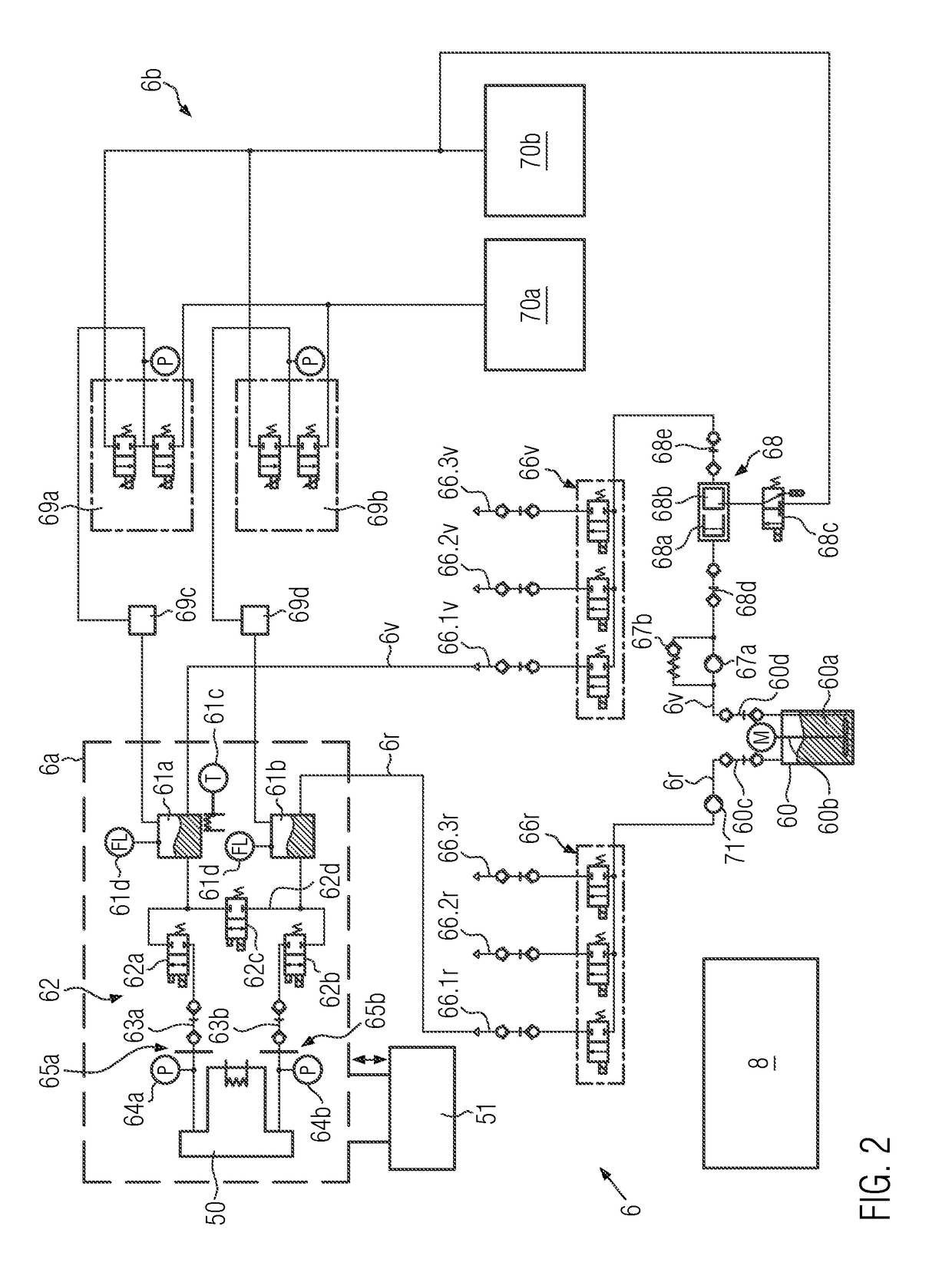
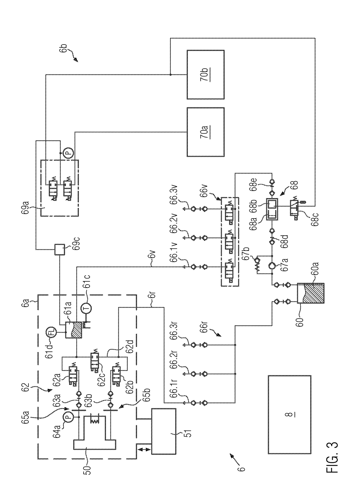
The patent describes a method for cleaning the ink supply system of a direct printing machine by interrupting the ink flow through the direct print head and creating a bypass line parallel to the direct print head. This allows for automatic rinsing of the ink supply system with printing ink during maintenance or startup, as well as removal of bubbles or foreign matter. The method also allows for increased pressure purge (shock cleaning) of the direct print head by opening the valves intermittently. This method results in a high quality of direct printing at lower ink supply cost. The ink flow can be produced via the direct print head with the valve terminal arranged between the at least one header tank and the direct print head, which allows for printing again in a normal printing operation. The direct printing process can be carried out with the direct printing machine described above.

Problems solved by technology

The disadvantage thereby is that with the maintenance of the direct print head or during the startup, the supply line and / or return line of the ink supply system must be disconnected; such a process proves to be time-consuming when subsequently restoring a closed ink flow.
In addition, automatic rinsing of the ink supply system or the direct print head is not possible.
This results in particularly low maintenance costs.

Method used


Image

  • Direct printing machine and method for printing containers with direct printing
  • Direct printing machine and method for printing containers with direct printing
  • Direct printing machine and method for printing containers with direct printing

Examples


Embodiment Construction

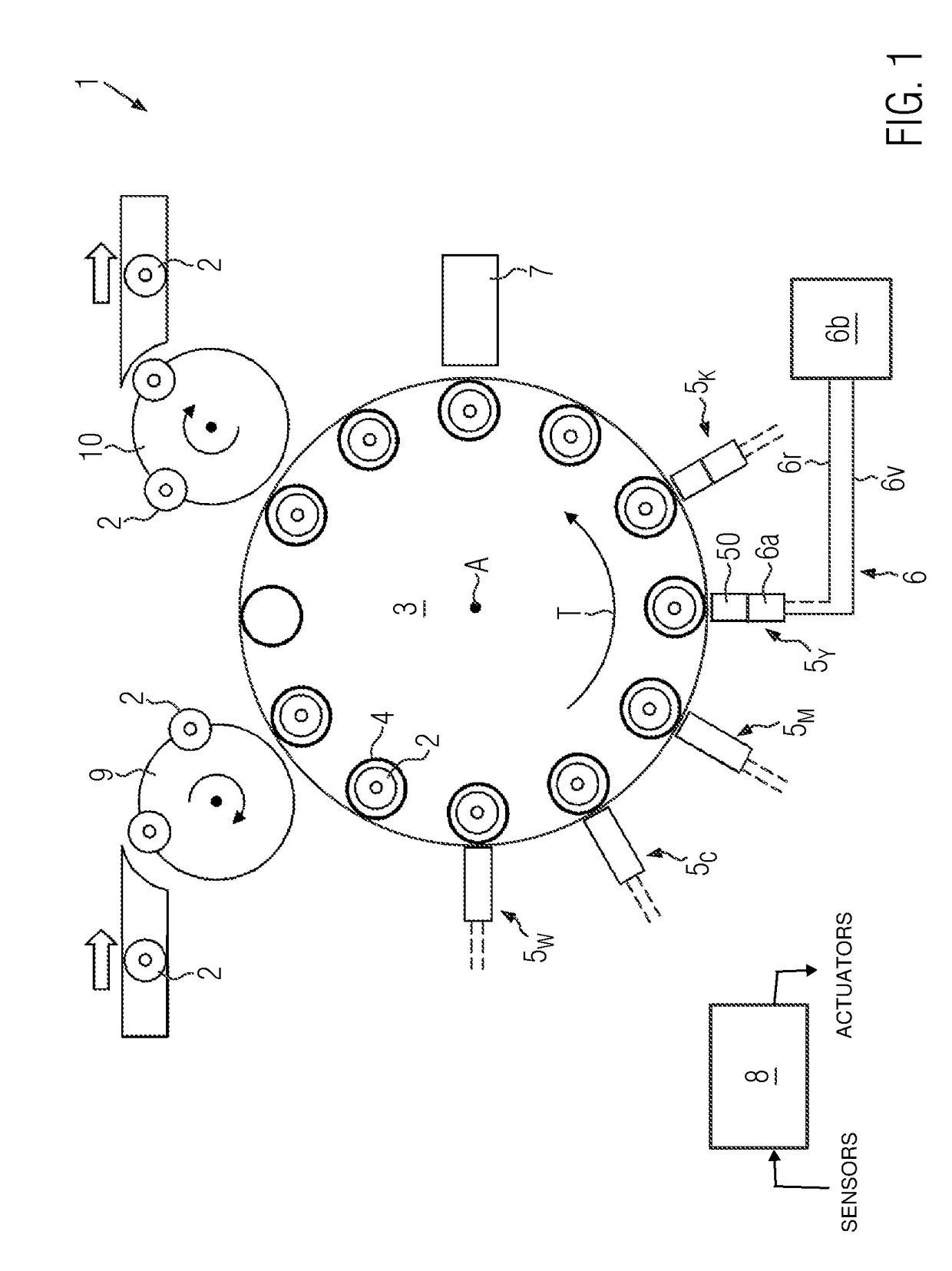
[0043]FIG. 1 shows in an overview an inventive embodiment of a direct printing machine 1 for printing containers 2 with direct printing. It can be seen that container 2, for example, coming from a filler and a capper, is fed to the conveyor 3 with the infeed starwheel 9.

[0044]The container receptacles 4 are arranged on conveyor 3, which are shown here only schematically. The container receptacles 4 can comprise, for example, a rotary plate and a centring bell to accommodate the container bottom or the mouth area of the respective container 2. The conveyor 3, for example, is designed as a carousel and rotates about the axis A, so that the containers 2 in the container receptacles 4 are conveyed in the transport direction T at the stationary direct printing stations 5W, 5C, 5M, 5Y, 5K.

[0045]The stationary direct printing stations 5W, 5C, 5M, 5Y, 5K, each comprising three direct print heads 50, are arranged around the conveyor 3. However, it is also conceivable that the stationary dire...


PUM


Abstract

A direct printing machine for printing containers with a direct print, having at least one stationary direct printing station with a direct print head, an ink supply system for supplying ink to the direct print head, and with a conveyor for conveying the containers past at the direct printing station, the ink supply system comprising a supply line and / or a return line for the printing ink, for producing ink flow from a supply tank to the direct print head and / or back, wherein the ink supply system comprises at least one header tank arranged in the supply line and / or the return line for setting a meniscus pressure of the printing ink, and a valve terminal is arranged between the header tank and the direct print head to interrupt the ink flow over the direct print head and to produce it in a bypass line.

Description

CROSS REFERENCE TO RELATED APPLICATION[0001]This application claims priority to German Patent Application No. 10 2017 215 475.6 entitled “DIRECT PRINTING MACHINE AND METHOD FOR PRINTING CONTAINERS WITH DIRECT PRINTING,” filed on Sep. 4, 2017, the entire contents of which is hereby incorporated by reference in its entirety for all purposes.TECHNICAL FIELD[0002]The present disclosure relates to a direct printing machine and a direct printing method for printing containers with direct printing.BACKGROUND AND SUMMARY[0003]Usually containers, such as beverage containers, are provided with a label in a labelling machine to identify the contents of the container and / or for advertising purposes.[0004]Recently, however, direct printing machines and methods are increasingly being applied, whereby, instead of or in addition to the labels, the containers are provided with direct printing according to the ink jet principle. This makes it possible to print the containers individually in a stream ...

Claims


Application Information

Patent Timeline
Patent Type & Authority Applications(United States)
IPC IPC(8): B41J2/175
CPCB41J2/17596B41J2/175B41J2/18B41J3/4073
Inventor REGENSBURGER, JOHANNESHANDSCHUH, EDUARDWAGNER, MARTINGETTE, VIKTOR
Owner KRONES AG
Learn More