
Methods And Systems For Conducting A Time-Marching Numerical Simulation Of A Deep Drawing Metal Forming Process For Manufacturing A Product or Part

Active Publication Date: 2019-02-28
ANSYS
View PDF0 Cites 2 Cited by
  • Summary
  • Abstract
  • Description
  • Claims
  • Application Information

AI Technical Summary

Benefits of technology

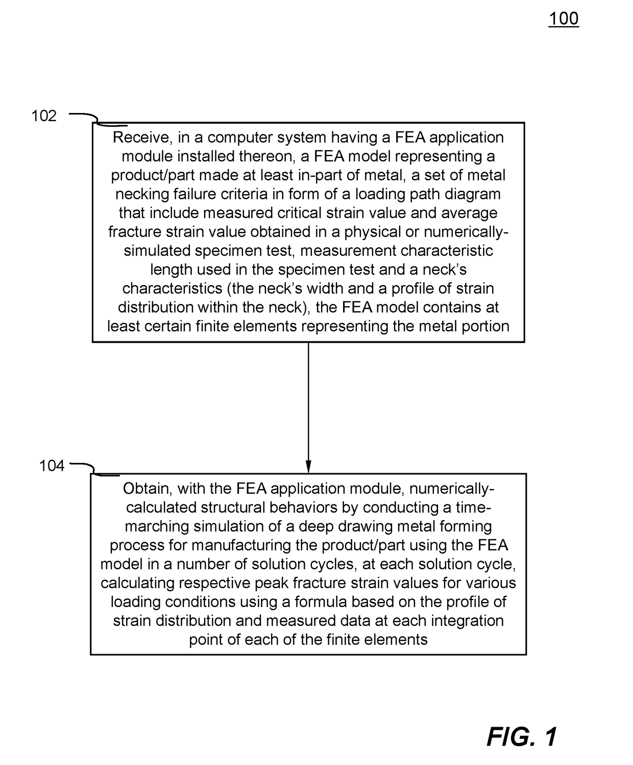
This patent describes a method and system for simulating a process of making products using metal forming techniques. The system uses a computer system and a finite element analysis model to predict the behavior of the metal during the process. The system takes into account various factors such as the strain on the metal, the size and shape of the product being made, and the characteristics of the metal. By calculating the strain and analyzing the distribution of strain within the material, the system can predict the likelihood of failure or deformation during the process. This information can be used to improve the manufacturing process and produce products with better quality.

Problems solved by technology

Due to the measurement dependency of the average fracture strain values, these prior art approaches often cause confusions and difficulties for preparing input data and lead to incorrect simulation because users need to prepare the failure criteria based on these artificial and ad hoc requirement.

Method used


Image

  • Methods And Systems For Conducting A Time-Marching Numerical Simulation Of A Deep Drawing Metal Forming Process For Manufacturing A Product or Part
  • Methods And Systems For Conducting A Time-Marching Numerical Simulation Of A Deep Drawing Metal Forming Process For Manufacturing A Product or Part
  • Methods And Systems For Conducting A Time-Marching Numerical Simulation Of A Deep Drawing Metal Forming Process For Manufacturing A Product or Part

Examples


Embodiment Construction

[0020]In the following description, numerous specific details are set forth in order to provide a thorough understanding of the invention. However, it will become obvious to those skilled in the art that the invention may be practiced without these specific details. The descriptions and representations herein are the common means used by those experienced or skilled in the art to most effectively convey the substance of their work to others skilled in the art. In other instances, well-known methods, procedures and components have not been described in detail to avoid unnecessarily obscuring aspects of the invention.

[0021]Reference herein to “one embodiment” or “an embodiment” means that a particular feature, structure, or characteristic described in connection with the embodiment can be included in at least one embodiment of the invention. The appearances of the phrase “in one embodiment” in various places in the specification are not necessarily all referring to the same embodiment...


PUM


Abstract

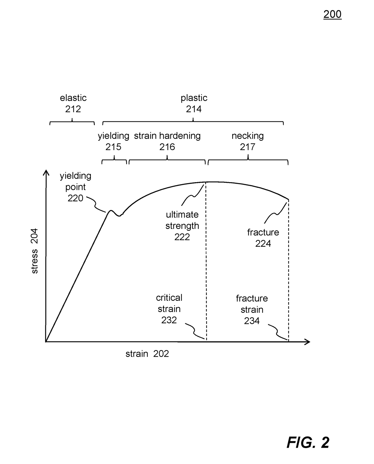
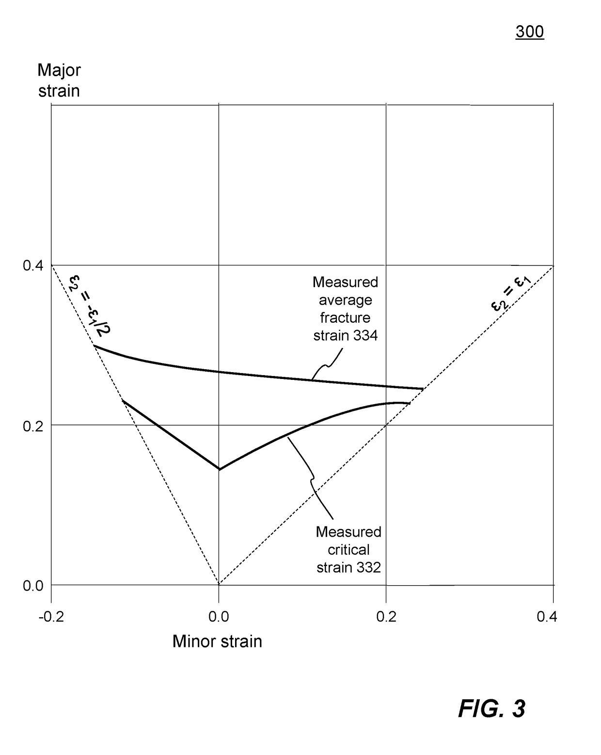
A FEA model representing a product / part with certain finite elements for metal portion, metal fracture failure criteria, a measurement characteristic length in a specimen test, and characteristics of a neck formed in the metal are received in a computer system. The metal fracture failure criteria contain respective measured critical strain value and average fracture strain value in various loading conditions. The characteristics of the neck include the neck's width and a profile of strain distribution within the neck's width. Respective peak fracture strain values are calculated for various loading conditions using a formula based on the profile of strain distribution, the neck's width, and measured critical strain value and average fracture strain value. Peak fracture strain values are used in each solution cycle of a time-marching simulation of a deep drawing metal forming process for manufacturing the product / part.

Description

CROSS-REFERENCE TO RELATED APPLICATIONS[0001]This application is a continuation-in-part (CIP) of a co-pending U.S. patent application Ser. No. 16 / 169,802 for “Methods And Systems For Conducting A Time-Marching Numerical Simulation Of A Deep Drawing Metal Forming Process For Manufacturing A Product or Part”, filed Oct. 24, 2018, which is a CIP of co-pending U.S. patent application Ser. No. 14 / 861,976 for “Methods And Systems For Conducting A Time-Marching Numerical Simulation Of A Structure Expected To Experience Metal Necking Failure”, filed on Sep. 22, 2015.[0002]This application is also a CIP of a co-pending U.S. patent application Ser. No. 15 / 157,301 for “Systems And Methods Of Deriving Peak Fracture Strain Values Of Metal Experiencing Fracture Failure”, filed May 17, 2016.FIELD[0003]The patent document relates generally to computer-aided engineering analysis. More particularly, the present document relates to methods and systems for conducting a time-marching numerical simulatio...

Claims


Application Information

Patent Timeline
IPC IPC(8): G06F17/50
CPCG06F17/5018G06F17/5086G06F2217/16G06F2217/42G06F30/17G06F2113/24G06F2111/10G06F30/23
Inventor ZHU, XINHAI
Owner ANSYS
Learn More