Vehicle control apparatus

a control apparatus and vehicle technology, applied in mechanical apparatus, transportation and packaging, propulsion parts, etc., can solve the problems of shifting shock, inability to easily control to a target value, shifting shock, etc., to reduce shifting shock, reduce shifting shock, and reduce the accuracy of detection

Active Publication Date: 2019-02-28
TOYOTA JIDOSHA KK +1
View PDF18 Cites 6 Cited by
  • Summary
  • Abstract
  • Description
  • Claims
  • Application Information

AI Technical Summary

Benefits of technology

The present invention provides a control apparatus for a vehicle that can reduce the shifting shock experienced during gear shifts in low-speed driving. Three modes of the invention are provided that select between power-on control and power-off control based on the actual input torque, with the power-off control being prioritized at lower running speeds to reduce shifting shock. Additionally, the upper limit value of the actual input torque can be changed based on factors such as vehicle speed or acceleration to ensure appropriate gear shifts and reduce the likelihood of shifting shock. Overall, this invention provides a more accurate and responsive control system for vehicles that improves the overall driving experience.

Problems solved by technology

By the way, in a control apparatus of the vehicle disclosed in JP-2004-293710A, where a shift-down action is executed with a running speed of the vehicle being in a low speed range, if the above-described determination is made based on the throttle opening degree, there is a risk that a shifting shock could be caused.
Specifically, since an accuracy of detection made by each rotating speed sensor is low in the low speed range, if the shift-down control is implemented in accordance with the shifting control rule corresponding to the power-on, which is selected based on the throttle opening degree, an engine rotating speed or the like cannot be easily controlled to a target value in process of the shift-down action, so that there is a risk that the shifting shock could be caused.

Method used


Image

  • Vehicle control apparatus
  • Vehicle control apparatus
  • Vehicle control apparatus

Examples


embodiment

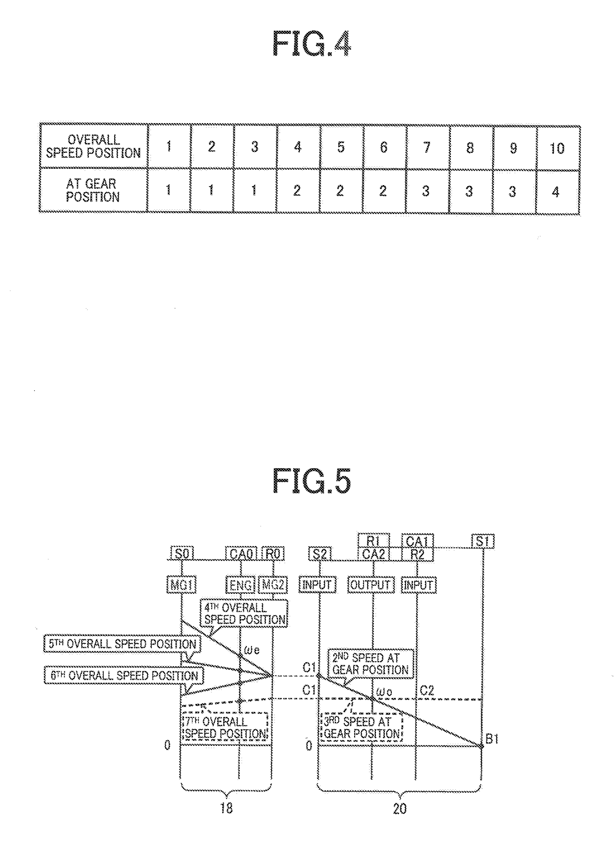
[0030]Reference is first made to FIG. 1, which is the schematic view showing an arrangement of a drive system 12 of a vehicle 10 to be controlled by a control apparatus according to the present invention, and major portions of the control apparatus to perform various controls of the vehicle 10. As shown in FIG. 1, the vehicular drive system 12 is provided with an engine 14 serving as a drive power source, an electrically-controlled continuously-variable transmission portion 18 (hereinafter referred to as “continuously-variable transmission portion 18”) connected directly indirectly via a damper (not shown) or any other device to the engine 14, and a mechanically-operated step-variable transmission portion 20 thereinafter referred to as “step-variable transmission portion 20”) connected to an output rotary member of the continuously-variable transmission portion 18. The continuously-variable transmission portion 18 and the step-variable transmission portion 20 are disposed in series ...


PUM


Abstract

A vehicle control apparatus selects one of a power-on control and a power-off control for execution of a shift-down action in a transmission of a vehicle, and implements the selected power-on or power-off control. When a running speed of the vehicle is not lower than a predetermined value, the control apparatus selects one of the power-on control and the power-off control, based on a target input torque that is to be inputted to the transmission. When the vehicle running speed is lower than the predetermined value, the control apparatus selects one of the power-on control and the power-off control, based on an actual input torque that is actually inputted to the transmission.

Description

[0001]This application claims priority from Japanese Patent Application No. 2017-167686 filed on Aug. 31, 2017, the disclosure of which is herein incorporated by reference in its entirety.FIELD OF THE INVENTION[0002]The present invention relates to a control apparatus for a vehicle including a drive power source and a transmission that constitutes a part of a power transmitting path between the drive power source and drive wheels of the vehicle.BACKGROUND OF THE INVENTION[0003]There is well known a vehicle that includes a drive power source and a transmission that constitutes a part of a power transmitting path between the drive power source and drive wheels. A vehicle including an engine and an automatic transmission, which is disclosed in JP-2004-293710A, is an example of this type of vehicle. This document discloses that a shift-up control or a shift-down control is implemented in accordance with one of shifting control rules corresponding to respective power-on and power-off of ...

Claims


Application Information

Patent Timeline
Patent Type & Authority Applications(United States)
IPC IPC(8): B60W20/30F16H61/02B60K6/547B60K6/40B60W10/06B60W10/08
CPCB60W20/30F16H61/0204B60K6/547B60K6/40B60W10/06B60W10/08B60W2520/10B60W2510/1025B60W2540/10B60W2710/1005B60W2710/0666B60W2710/083B60Y2200/92B60K6/365B60K6/445B60W10/115F16H59/18F16H59/42F16H59/44F16H59/46F16H61/0437F16H2059/147Y02T10/62
Inventor GOTO, JUNKUMAZAKI, KENTASHIIBA, KAZUYUKIMATSUBARA, TOORUYOSHIKAWA, MASATOOKASAKA, KAZUOMIKAYUKAWA, ATSUSHISUYAMA, DAISUKEMAEDA, MITSURU
Owner TOYOTA JIDOSHA KK
Why Eureka
Try Eureka