
Coil extension element

a technology of extension element and voice coil, which is applied in the direction of diaphragm materials, electrical transducers, transducer diaphragms, etc., can solve the problems of reducing the excursion space of the voice coil, reducing the sensitivity or air pumping capacity of the membrane, and the need of common voice coils, so as to reduce the total harmonic distortion (thd) of the loud speaker and increase the acoustic performance

Active Publication Date: 2019-02-14
SOUND SOLUTIONS INTERNATIONAL COMPANY LTD
View PDF3 Cites 0 Cited by
  • Summary
  • Abstract
  • Description
  • Claims
  • Application Information

AI Technical Summary

Benefits of technology

The present invention provides a loudspeaker that improves the sound quality and reduces distortion. This is achieved by using a voice coil design that eliminates distortion in the area of highest magnetic field intensity. This design allows for increased performance without changing the overall height of the voice coil required for installation.

Problems solved by technology

This glue overflow reduces the available space for excursion of the voice coil.
This reduces either sensitivity or air pumping capacity of the membrane.
A particular drawback of known loudspeakers is that common voice coils need to have windings far away from the maximum magnetic field to allow the necessary excursion.
This reduces sensitivity of the loudspeaker and increases undesired Total Harmonic Distortion (THD).

Method used


Image

  • Coil extension element
  • Coil extension element

Examples


Embodiment Construction

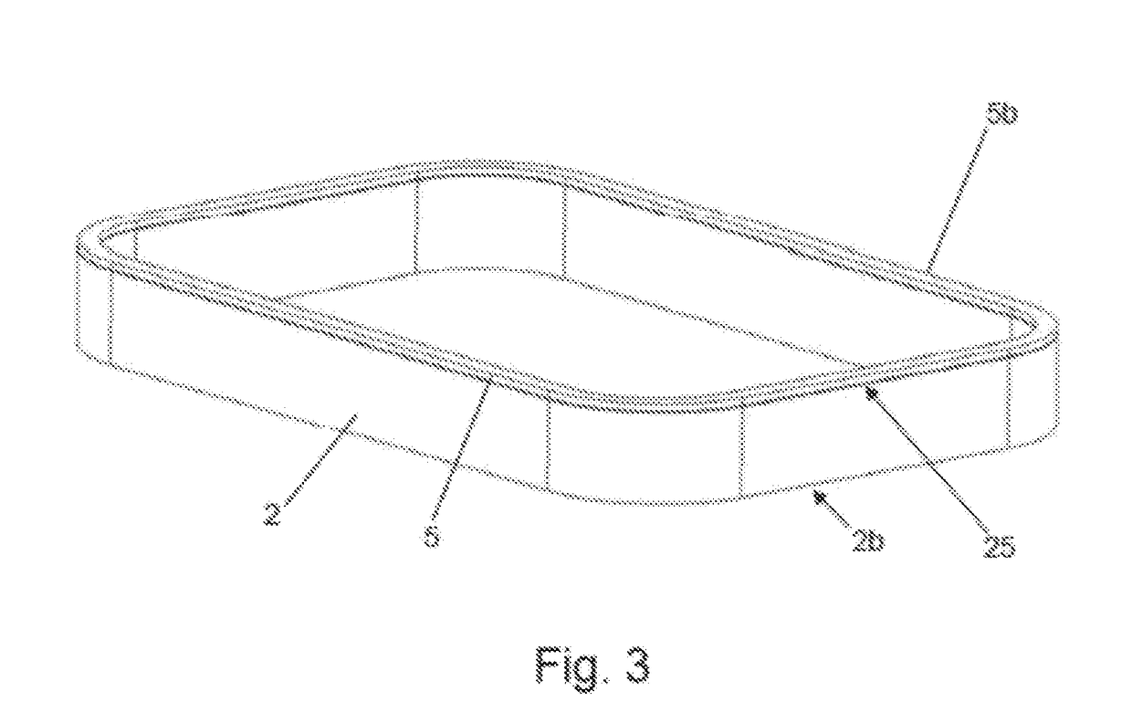
[0028]FIG. 1 shows a schematic representation of an embodiment of a loudspeaker driver 1. Loud speaker driver 1 comprises a voice coil 2. An electrical signal to drive the voice coil 2 is fed into the voice coil 2 through leads which are nit shown. The voice coil 2 of assembled loudspeaker driver 1 is attached to a membrane 3. A thickness of the membrane 3 can be constant over its entire surface. The membrane 3 is typically built out of one or more layers of material, such as, for example, Ethere Ketone (PEEK), Acrylate and / or Thermoplastic Elastomeric (TPE), Polyetherimide (PEI), and / or other materials known in the art.

[0029]Loudspeaker driver 1 includes a magnet system 4 which may comprise a perimeter magnet assembly 4a and a center magnet assembly 4b. Perimeter magnet assembly 4a may include magnets 4c, 4d arranged on sides of the loudspeaker driver 1 which may be of rectangular shape and a ring plate 4e fixed to magnets 4c, 4d. Center magnet assembly 4a includes a magnet 4f arra...


PUM


Abstract

A dynamic loudspeaker driver comprising a magnet-system; a membrane; the membrane being movably mounted with respect to the magnet-system; at least one voice coil attached to the membrane and operatively coupled with the magnet-system, wherein the voice coil comprises an upper edge facing the membrane and a lower edge being arranged opposite the upper edge of the voice coil; at least one voice coil extension element comprising an upper surface facing the membrane and a lower surface facing the upper edge of the voice coil, wherein the lower surface of the voice coil extension element is attached the upper edge of the voice coil while the upper surface of the voice coil extension element is attached to the membrane.

Description

PRIORITY[0001]This patent application claims priority from Austrian Patent Application No. A50670 / 2017, filed on Aug. 11, 2017, the disclosure of which is incorporated herein, in its entirety, by reference.BACKGROUND OF THE INVENTIONa. Field of the Invention[0002]The present invention relates to a dynamic loudspeaker driver with enhanced acoustic properties. This invention furthermore relates to a loudspeaker and to a micro speaker optimized for high acoustic output and located within a small volume of a mobile device, such as a mobile phone, a tablet, a gaming device, a notebook or similar device. The invention also relates to a method of producing a loudspeaker driver with enhanced acoustic properties.b. Background Art[0003]A dynamic loudspeaker driver usually comprises a magnet system, a membrane movably mounted with respect to the magnet system, and a voice coil attached to the membrane. The magnet system comprises a magnet and the voice coil is operatively coupled with the magn...

Claims


Application Information

Patent Timeline
Patent Type & Authority Applications(United States)
IPC IPC(8): H04R9/06H04R7/04H04R9/02H04R9/04H04R7/18H04R31/00
CPCH04R9/06H04R7/04H04R9/025H04R9/046H04R7/18H04R31/003H04R2307/00H04R2400/11
Inventor HEIDINGER, FRANZKLEIN, ERICHTOMAS, ERNST
Owner SOUND SOLUTIONS INTERNATIONAL COMPANY LTD
Learn More