Contact charging system, power feeding device, power receiving device, and contact charging method

Inactive Publication Date: 2019-02-14
HONDA MOTOR CO LTD
View PDF7 Cites 3 Cited by
  • Summary
  • Abstract
  • Description
  • Claims
  • Application Information

AI Technical Summary

Benefits of technology

The present invention is aimed at providing a system, device, and method for contact charging that prevents damage to the power feeding and receiving terminals even at high charging powers. The technical effect achieved is that the point of contact between the terminals is evenly distributed, preventing adhesion and damage during charging.

Problems solved by technology

It is, however, problematic when a driving battery of an electric vehicle is charged.
Thus, if charging is performed at high power while the power feeding element and the power receiving element are in contact with each other in a non-movable manner during charging, the point of contact between the power feeding element and the power receiving element could produce heat, whereby the elements could be damaged.
The charging time can be shortened by using high charging power; however, significant heat could still be produced at the point (position) of contact between the power feeding terminal and the power receiving terminal and cause damage to the terminals.

Method used


Image

  • Contact charging system, power feeding device, power receiving device, and contact charging method
  • Contact charging system, power feeding device, power receiving device, and contact charging method
  • Contact charging system, power feeding device, power receiving device, and contact charging method

Examples


first embodiment

2. First Embodiment

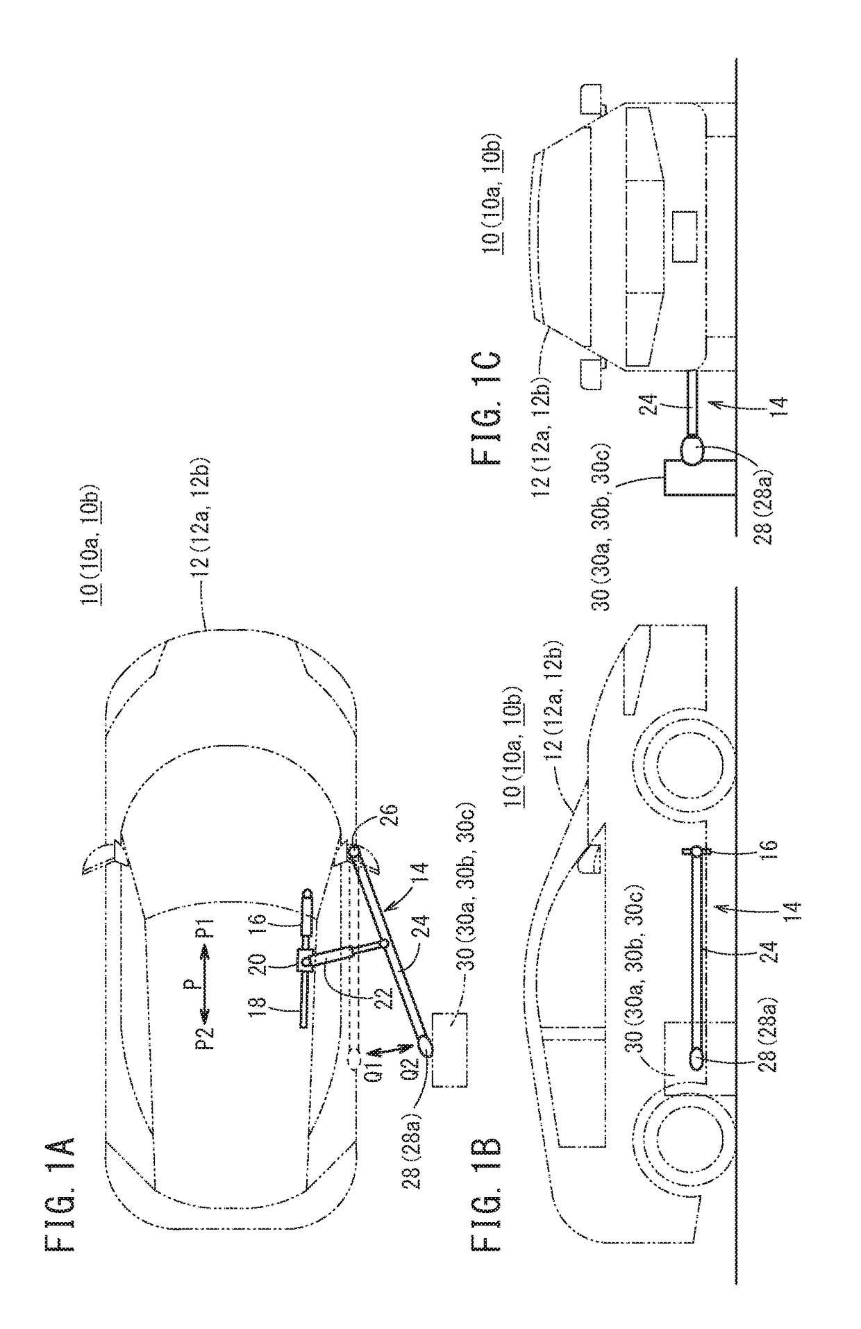
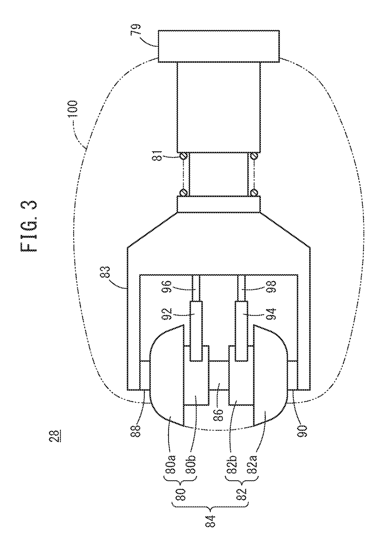
[0046]Using FIGS. 2 to 4, the power feeding device 30 and the power receiving head 28 used in the contact charging system 10 according to the first embodiment are described. In the first embodiment, in charging of the high-voltage battery 102, a feeding-side motor 38 is rotated in a state in which the power feeding terminal 36 and the power receiving terminal 84 are pressed against each other, thereby transmitting motive power from the power feeding terminal 36 to the power receiving terminal 84 to cause both the power feeding terminal 36 and the power receiving terminal 84 to rotate.

[2.1. Configuration of Power Feeding Device 30]

[0047]Using FIGS. 2 and 4, the configuration of the power feeding device 30 is described. The power feeding device 30 according to the first embodiment includes the power feeding terminal 36 having a pair of terminals capable of rotating about a first rotation shaft (a first upper rotation shaft 52, a first lower rotation shaft 56), namel...

second embodiment

3. Second Embodiment

[0068]Using FIGS. 6 to 8, a power feeding device 30a and a power receiving head 28a used in a contact charging system 10a according to the second embodiment (see FIG. 1A, for instance) are described. In the second embodiment, in charging of the high-voltage battery 102, a receiving-side motor 110 is rotated in a state in which the power feeding terminal 36 and the power receiving terminal 84 are pressed against each other, thereby transmitting motive power from the power receiving terminal 84 to the power feeding terminal 36 to cause both the power feeding terminal 36 and the power receiving terminal 84 to rotate.

[3.1. Configuration of Power Feeding Device 30a]

[0069]Using FIGS. 6 and 8, the configuration of the power feeding device 30a is described. The power feeding device 30a according to the second embodiment includes the power feeding terminal 36 having a pair of terminals capable of rotating about the first rotation shaft (the first upper rotation shaft 52, ...

third embodiment

4. Third Embodiment

[0083]In the third embodiment, a power feeding device 30b and an electric vehicle 12b are interconnected via wireless communication, and a command signal for applying voltage and a command signal for stopping voltage application are sent from the side of the electric vehicle 12b to the side of the power feeding device 30b.

[4.1. Configuration of Power Feeding Device 30b]

[0084]Using FIG. 9, the configuration of the power feeding device 30b is described. The configuration of the power feeding device 30b has many in common with that of the power feeding device 30a according to the second embodiment shown by FIG. 8. Thus, for the power feeding device 30b shown by FIG. 9, components that are common to the power feeding device 30a are given the same reference characters and are not described again. The power feeding device 30b shown by FIG. 9 is different from the power feeding device 30a shown by FIG. 8 in that the power feeding device 30b uses a feeding-side communica...


PUM


Abstract

Provided are a contact charging system, a power feeding device, a power receiving device, and a contact charging method that prevent damage to a power feeding terminal and a power receiving terminal, even when the charging power is high power. When charging a high-voltage battery, a power feeding-side motor or a power receiving-side motor is rotated in a state with a power feeding terminal and a power receiving terminal pressed against each other, and power is thereby transmitted from one of the power feeding terminal and the power receiving terminal to the other. In a state with both the power feeding terminal and the power receiving terminal rotated in this manner, electric power is supplied from the power feeding terminal to the power receiving terminal.

Description

TECHNICAL FIELD[0001]The present invention relates to a contact charging system for charging a battery provided on the side of a power receiving device by use of a power feeding device, and a method for the same.BACKGROUND ART[0002]Japanese Laid-Open Patent Publication Nos. 07-283852 and 2006-049123 both describe chargers for charging a mobile phone battery. These inventions allow rotation of a power feeding element and / or a power receiving element so that the point of contact between the power feeding element and the power receiving element is not concentrated at a single point. Such a configuration makes the power feeding element and / or the power receiving element resistant to degradation due to abrasion.[0003]Japanese Laid-Open Patent Publication Nos. 2012-034543 and 2011-135739 describe structures and / or systems for charging a battery of an electric automobile or a plug-in hybrid automobile (referred to as an electric vehicle). As shown by these publications, when a driving batt...

Claims


Application Information

Patent Timeline
IPC IPC(8): B60L11/18B60L5/40H02J7/00
CPCB60L11/1816B60L5/40H02J7/007B60L11/1827H02J7/00B60L5/36B60L5/42B60L53/16B60L53/31B60L53/32B60L53/60B60L53/18Y02T90/12B60L53/35Y02T10/70
Inventor TAJIMA, TAKAMITSUMATSUMOTO, SOICHIRO
Owner HONDA MOTOR CO LTD
Why Eureka
Try Eureka