
Ultrasonic oscillator unit

a technology of ultrasonic oscillator and ultrasonic observation part, which is applied in the direction of mechanical vibration separation, catheter, printed circuit non-printed electric components association, etc., can solve the problems of complicated handling of cables within the ultrasonic observation part with a small external diameter, complicated wiring within the ultrasonic observation part, etc., to achieve simple configuration, improve workability during wiring, and use efficiently

Active Publication Date: 2019-02-14
FUJIFILM CORP
View PDF0 Cites 0 Cited by
  • Summary
  • Abstract
  • Description
  • Claims
  • Application Information

AI Technical Summary

Benefits of technology

The invention aims to solve issues in the current ultrasonic technology by providing an ultrasonic oscillator unit that is small-sized, easy to work with, and has a low risk of disconnection or disconnection. The unit has a simple wiring structure that improves its workability and success rate of manufacturing. Additionally, the invention provides a wiring structure that is suitable for use in an ultrasonic endoscope. Overall, this invention improves the overall performance of ultrasonic technology.

Problems solved by technology

For example, the number of channels is as large as 48 to 192, the external diameter of ultrasonic observation part is small, and expensive, extremely fine cables are used as the cables.
Therefore, in the current situation, wiring within the ultrasonic observation part is a complicated task, and numerous wiring lines are manually wired within a small distal end part.
For this reason, the handling of the cables within the ultrasonic observation part with a small external diameter is complicated, and high filling is required.
That is, since it is necessary to wire the cables in high density within the ultrasonic observation part in addition to the handling of the cables being complicated, this becomes a cause that the workability is poor and the manufacturing costs of the ultrasonic endoscope become high.
In spite of size reduction of the ultrasonic observation part being required in order to improve the workability and reduce the burden on the patient, as described above, there is a problem that the size reduction of the ultrasonic observation part is very difficult from viewpoints of the manufacture stability of the ultrasonic observation part, and the manufacturing costs thereof.
Therefore, there is a problem that the wiring structure of the cable bundle and the flexible printed wired board is complicated.
Even though the ultrasonic oscillator array, the cable bundle, and the flexible printed wired board are connected to each other by thermocompression bonding, there is still a problem in the workability of wiring.
Particularly, in JP4445764B, there are problems that, during the manufacture of the ultrasonic oscillator unit, a burden is applied on a cable in a case where the flexible printed wired board is folded up multiple times, and the cable wiring line to which the burden is applied is disconnected.
In this structure, there are problems that the manufacture is significantly difficult and the success rate of the manufacture is not high.

Method used


Image

  • Ultrasonic oscillator unit
  • Ultrasonic oscillator unit
  • Ultrasonic oscillator unit

Examples


Embodiment Construction

[0030]An ultrasonic oscillator unit related to the invention will be described in detail with reference to a preferred embodiment illustrated in the attached drawings.

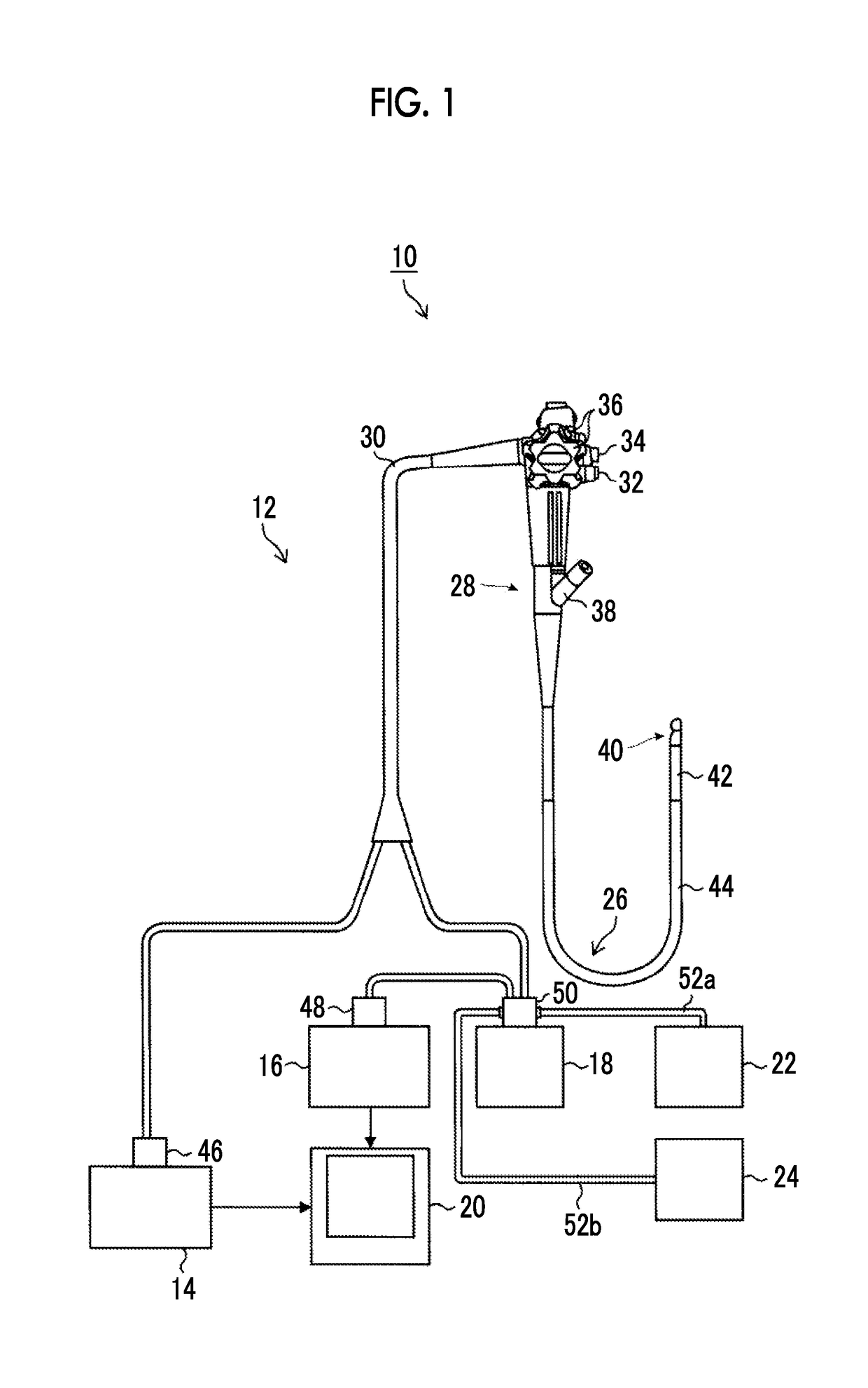
[0031]FIG. 1 illustrates a schematic configuration view illustrating an example of the configuration of an ultrasonic inspection system using an ultrasonic endoscope to which an ultrasonic oscillator unit of the invention is applied.

[0032]The ultrasonic inspection system illustrated in FIG. 1 allows observation of the gallbladder or the spleen that is difficult in the ultrasonic inspection from the body surface of a subject, such as a patient, via alimentary canals, such as the esophagus, the stomach, the duodenum, the small intestine, and the large intestine that are body cavities of the subject, includes the ultrasonic oscillator unit of the invention, and acquires an ultrasound image of a region to be observed of the subject while inserting the ultrasonic endoscope having an ultrasonic observation part and an endosc...


PUM


Abstract

A ultrasonic oscillator unit including an ultrasonic oscillator array in which a plurality of oscillators are arranged in a circular-arc shape; an electrode part that is provided on at least one end surface of the plurality of oscillators perpendicular to a longitudinal direction thereof and that is electrically connected with the oscillators; a backing material layer that is disposed on a rear surface of the ultrasonic oscillator array; and a cable wiring part including a flexible printed wired board. The flexible printed wired board includes a cable connecting part that extends to a lower side of the backing material layer, is separated into a plurality of belt-like pieces, and has, in a comb shape, a plurality of strip-like electrode parts in which at least one electrode pad is linearly disposed in the longitudinal direction of each of the belt-like pieces.

Description

CROSS-REFERENCE TO RELATED APPLICATIONS[0001]This application is a Continuation of PCT International Application No. PCT / JP2017 / 007403 filed on Feb. 27, 2017, which claims priority under 35 U.S.0 § 119(a) to Japanese Patent Application No. 2016-091934 filed on Apr. 28, 2016. Each of the above application(s) is hereby expressly incorporated by reference, in its entirety, into the present application.BACKGROUND OF THE INVENTION1. Field of the Invention[0002]The present invention relates to an ultrasonic oscillator unit having an ultrasonic oscillator wiring structure for realizing a small-sized ultrasonic oscillator.2. Description of the Related Art[0003]Ultrasonic endoscopes are ones in which an ultrasonic observation part is provided at a distal end part of an ultrasonic endoscope with observation of the gallbladder or the pancreas by an alimentary canal as a main purpose. In order to safely insert the ultrasonic endoscope into the alimentary canal, an optical sensor, illumination m...

Claims


Application Information

Patent Timeline
IPC IPC(8): B06B3/04H03B17/00H03B1/02H05K1/18H05K1/02
CPCB06B3/04H03B17/00H03B1/02H05K1/189H05K1/028A61B8/12A61B8/4494A61B8/445A61B1/0011A61B1/00114
Inventor YAMAMOTO, KATSUYAMORIMOTO, YASUHIKO
Owner FUJIFILM CORP
Learn More