
Fastening System

a technology of fastening system and fastening plate, which is applied in the field of fastening plate, can solve the problems of reducing the strength of parts, affecting the performance of parts, and affecting the quality of parts, so as to reduce the use of materials and increase the strength of parts

Inactive Publication Date: 2019-02-07
SMARTSCREW PTY LTD
View PDF4 Cites 3 Cited by
  • Summary
  • Abstract
  • Description
  • Claims
  • Application Information

AI Technical Summary

Benefits of technology

The invention is a system that includes a spherical-shaped fastener seat with the same radius of curvature as the fastener head. This ensures a tight and secure fastening of the prosthetic component to the anchor. The system also allows for easier installation of the fastener and provides a more accurate and direct machining of the fastener seat. The installation channel can be widened to create greater space for the cutting tool. The system can be used in biological applications, such as in the oil and gas industry, for fixed mechanical components, reducing material usage and increasing part strength.

Problems solved by technology

This is because living bone tissue, which is continually being dissolved and redeposited by the body, tends to disappear unless it is maintained under the appropriate loading level.
The problem with using dental adhesive is that if the prosthesis needs to be removed or replaced the entire prosthesis often needs to be destroyed.
However, when such a prosthetic implant is implanted into a young patient, it is likely that one or more revision operations will have to be performed during the lifetime of the patient.
It is highly undesirable to subject patients repeatedly to the trauma of such a major surgical procedure as is required to replace a failed prosthetic implant.
The problems sought to be overcome by the prosthetic system described hereafter is that manufacturing such prosthetic devices as those described above is complex and expensive, and at times prone to failure in that unintentional detachment inside the body can occur.

Method used


Image

  • Fastening System
  • Fastening System
  • Fastening System

Examples


Embodiment Construction

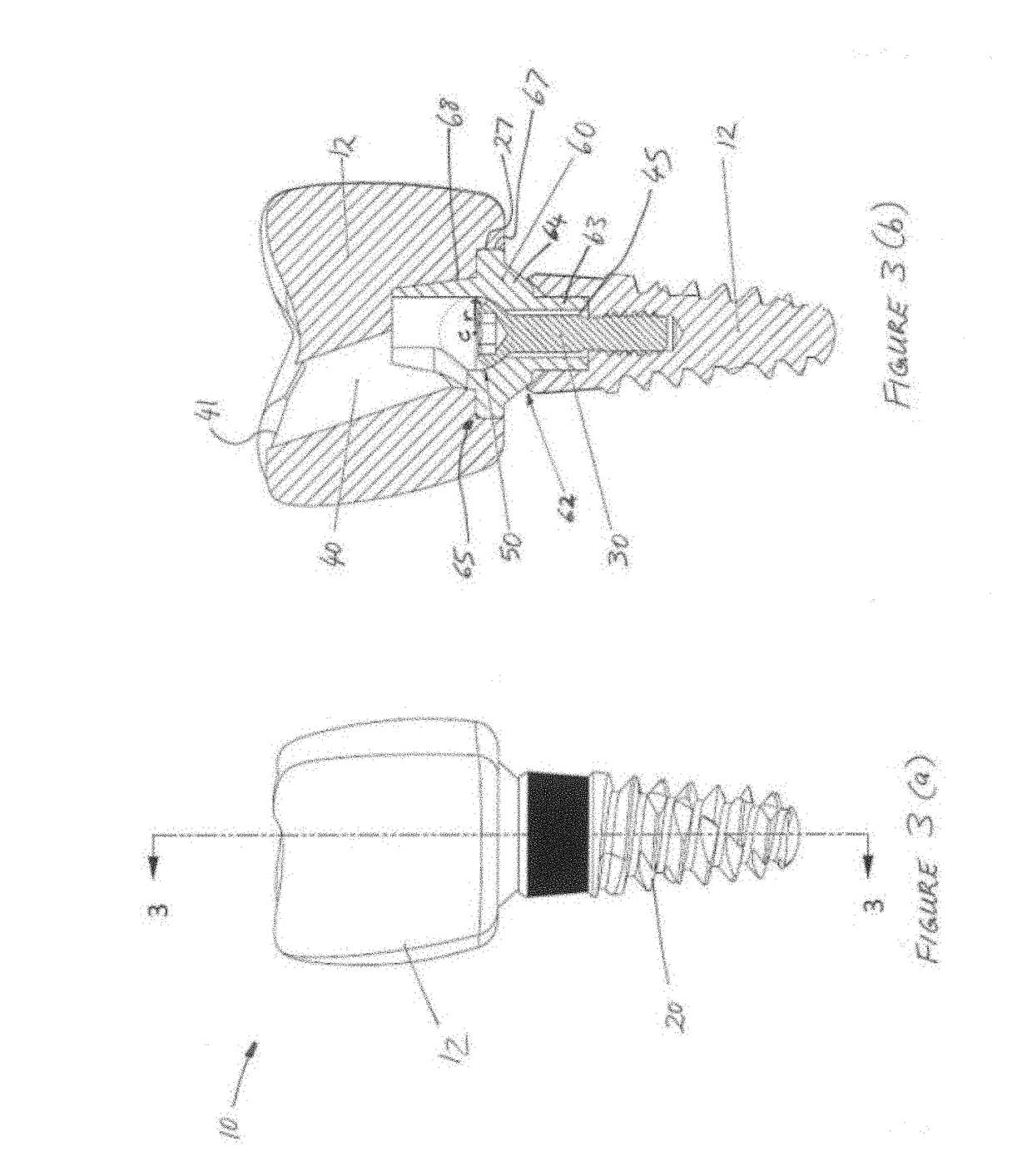
[0054]A prosthetic system is illustrated in FIGS. 1(a) to 4(b) and is generally denoted by the reference numeral 10. The prosthetic system 10 described herein is adapted to be fixed to an anchor 20 that is itself fixed into bone of a patient. Referring to FIGS. 1(a) and (b), exemplifying a dental prosthetic system, the prosthetic system 10 comprises a prosthetic component 12 having an upper part 15 that is the part of the component that will be exposed above a patient's bone line once attached to the anchor 20. At a lower part 14, the prosthetic component 12 narrows down to a collar 16 that is adapted to locate in an interfacing recess 21 of the anchor 20. The collar 16 and anchor recess 21 are complementarily profiled to mesh one inside the other. Specifically, a shoulder 17 transitions from the upper part 15 of the prosthetic component 12 to collar 16 at the lower part 14 of the prosthetic component, which lower part defines an anchor interface side 18 which, in use, is hidden fro...


PUM


Abstract

A system for fixing a prosthetic component to an anchor implanted in the bone of a patient. The prosthetic component includes a fixing channel and an installation channel. The fixing channel opens to an engagement collar configured to engage with a bone anchor. The installation channel opens from an outer surface of the prosthetic and communicates with the fixing channel. The installation channel permits placement of a fastener therethrough into the fixing channel to secure the prosthetic to the bone anchor. The axes of the fixing channel and the installation channel intersect at a point which lies within the radius of a fastener seat which is configured to engage a head of the fastener when the fastener is placed into the fixing channel.

Description

[0001]The present invention relates to a system for fixing a prosthesis to an anchor / implant, and a method of assembling a prosthetic system.BACKGROUND[0002]The use of prosthetic implants for surgical implantation in or on a bone of a patient is long established. Thus, in the case of a damaged or diseased hip joint, implantation of a prosthetic femoral implant, a prosthetic acetabular implant, or both, is a common surgical procedure. Another operation frequently performed by orthopaedic surgeons is knee replacement, in which a tibial implant is inserted in the top of a patient's tibia, while one or both condylar surfaces of the patient's femur may be replaced at the same by corresponding femoral implants. In case of accidental fracture of long bones bone plates may be used to stabilise and strengthen the bones. Shoulder, finger, ankle, and elbow replacement prostheses are also known.[0003]Another use of prosthetic implants is in dentistry. A dental prosthesis is a dental device fitt...

Claims


Application Information

Patent Timeline
IPC IPC(8): A61F2/30A61C8/00
CPCA61F2/30749A61F2/30734A61C8/0068A61F2/389A61F2002/30112A61F2002/30421A61B17/86A61F2002/30476A61F2002/30433A61F2002/3085A61F2002/30878A61F2250/0037A61F2002/4631A61F2230/0004A61F2002/30604A61C13/225A61C8/0022A61C8/0025A61F2/38A61F2002/30245
Inventor ELIOPOULOS, MICHAELWILDOER, MATTHEWPOWDERLY, NARAYAN
Owner SMARTSCREW PTY LTD
Learn More