
Spot-welded joint and spot welding method

a spot welding and joint technology, applied in welding equipment, welding/soldering/cutting articles, manufacturing tools, etc., can solve problems such as difficulty in determining joint strength, increased or reduced and increased strength of welded joints. to achieve the effect of improving the cross tensile strength of spot welding joints

Active Publication Date: 2019-01-31
NIPPON STEEL CORP
View PDF0 Cites 1 Cited by
  • Summary
  • Abstract
  • Description
  • Claims
  • Application Information

AI Technical Summary

Benefits of technology

The present invention can make the strength of a spot-welded joint stronger in steel plates that are 750 MPa to 2500 MPa in tensile strength.

Problems solved by technology

When a plurality of pieces of steel plates including at least one piece of steel plate whose tensile strength is 750 MPa or more are spot-welded, a strength of a welded joint becomes a problem.
Therefore, a problem regarding a joint strength is difficult to occur, in the spot-welded joint formed of the steel plates each having the tensile strength of 270 MPa to 600 MPa.
However, the CTS in a spot-welded joint formed of a plurality of pieces of steel plates including at least one piece of steel plate whose tensile strength is 750 MPa or more, does not increase or reduces even if the tensile strength of the steel plates increases.
However, in this method, there is a need to cause a martensite transformation to be almost completed before performing the tempering energization.
Accordingly, a long cooling time becomes required after the main energization is finished.
However, in this method, another process is required after the welding, and thus an operating procedure becomes complicated.
However, in this method, when a post-energization time is lengthened, a nugget diameter is only enlarged, and a structure becomes the same as that obtained in conventional welding.
However, in this method, the applicable steel plate is limited.
In addition, in this method, it takes a long time to perform the welding, and thus the productivity is low.
However, when a fracture occurs on the outside of the nugget, the structure of the nugget makes no contribution, and thus the definition related to the microstructure has no meaning.
However, in this method, a study regarding the time between the main welding and the post-energization has not been sufficiently conducted, and thus the method does not contribute to the improvement of the joint strength.

Method used

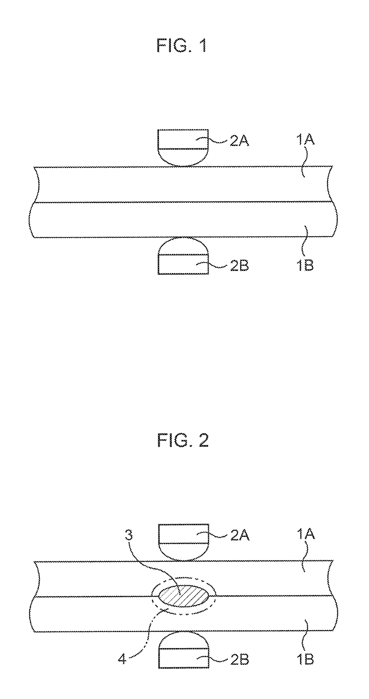
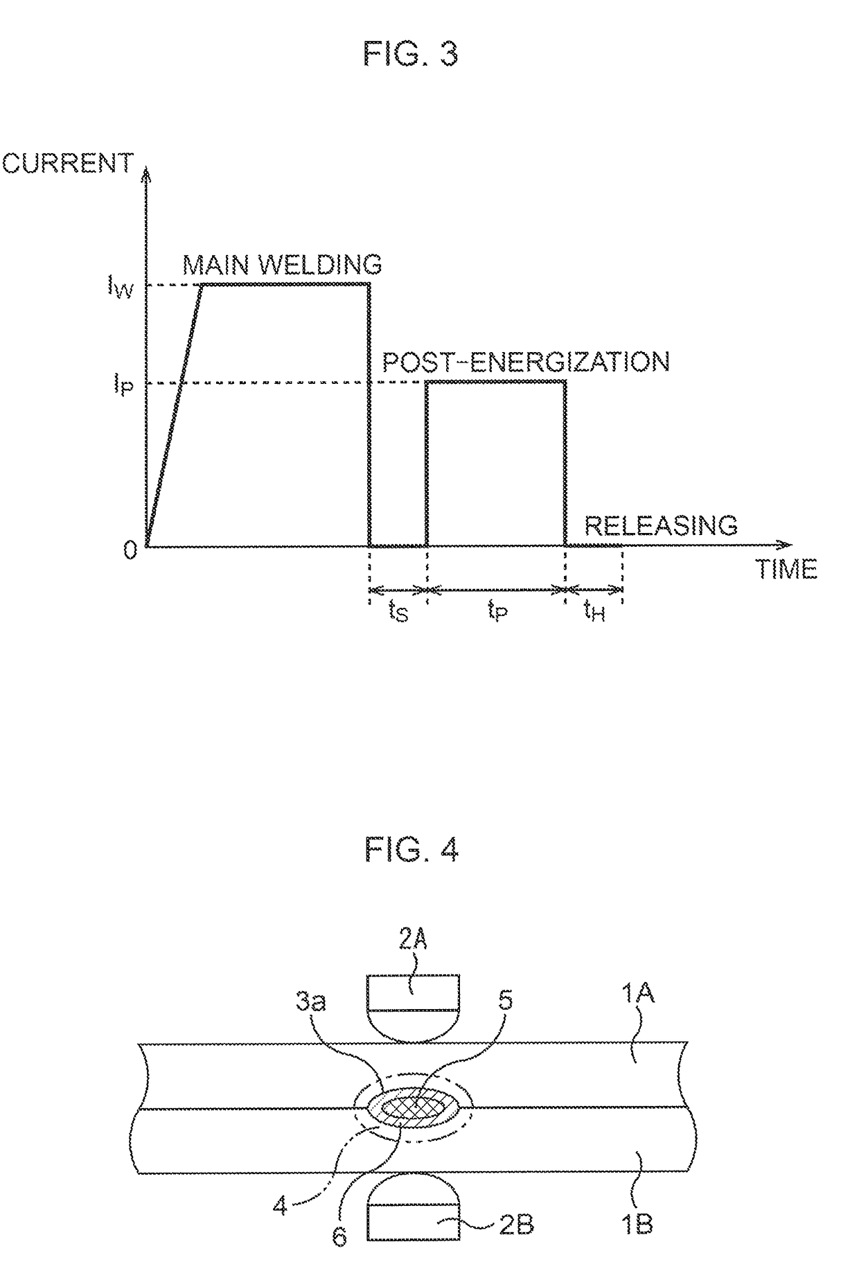
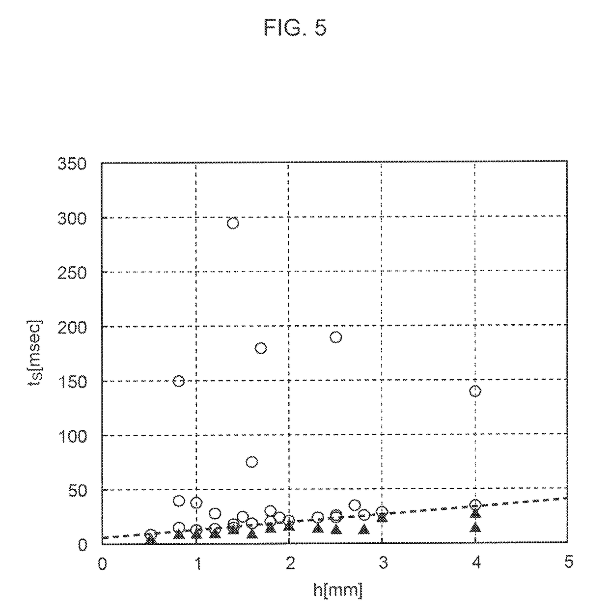

Image

  • Spot-welded joint and spot welding method
  • Spot-welded joint and spot welding method
  • Spot-welded joint and spot welding method

Examples


examples

[0252]Next, examples of the present invention will be described. Conditions in the examples are conditional examples employed for confirming applicability and effects of the present invention, and the present invention is not limited to the conditional examples. The present invention can employ various conditions as long as the object of the present invention is achieved without departing from the gist of the present invention.

[0253]Steel plates A, B, and C represented in Table 1 were prepared. The steel plate A is obtained by applying Al plating to a surface of a hot-stamped steel plate having a plate thickness of 2.0 (mm) and a tensile strength in the class of 1470 MPa. The steel plate B is obtained by applying Al plating to a surface of a hot-stamped steel plate having a plate thickness of 1.6 (mm) and a tensile strength in the class of 1470 MPa. The steel plate C is obtained by applying Zn plating to a surface of a hot-stamped steel plate having a plate thickness of 1.4 (mm) and...


PUM

PropertyMeasurementUnit
tensile strengthaaaaaaaaaa

Abstract

By obtaining a spot-welded joint being a spot-welded joint formed by overlapping a plurality of pieces of steel plates (1A, 1B) and performing spot welding on the steel plates, including a high-strength steel plate whose tensile strength is 750 (MPa) to 2500 (MPa), being at least one piece of steel plate out of the plurality of pieces of steel plates, in which a carbon equivalent Ceq of the high-strength steel plate is 0.20 mass % to 0.55 mass %, and ten or more of iron-based carbides in each of which a length of a longest portion is 0.1 (μm) or more exist in a square region 103 within a heat-affected zone 4 of a cross section that passes through a center of a welding mark, and is cut along a plate thickness direction of the steel plates (1A, 1B), a cross tensile strength of the spot-welded joint to be formed is improved.

Description

[0001]This application is a Divisional of U.S. application Ser. No. 14 / 889,111, filed Nov. 4, 2015, which is the U.S. National Phase of PCT / JP2014 / 064616, filed Jun. 2, 2014, which claims priority under 35 U.S.C. 119(a) to Japanese Patent Application No. 2013-118886, filed Jun. 5, 2013, the contents of all of which are incorporated by reference, in their entirety, into the present application.TECHNICAL FIELD[0002]The present invention relates to a joint formed by overlapping a plurality of pieces of steel plates and performing spot welding on the steel plates.BACKGROUND ART[0003]In recent years, a reduction in weight of a vehicle body has been demanded for achieving a fuel efficiency and a CO2 emission reduction in an automobile field. Further, in order to improve a collision safety, it has been demanded to increase a strength of members of a vehicle body. In order to fulfill these demands, it is effective to use a high-strength steel plate for a vehicle body, components and the lik...

Claims


Application Information

Patent Timeline
Patent Type & Authority Applications(United States)
IPC IPC(8): B23K11/11B23K11/16B23K103/04
CPCB23K2103/04B23K11/115B23K11/16B23K11/11
Inventor WAKABAYASHI, CHISATOWATANABE, FUMINORIFURUSAKO, SEIJIMIYAZAKI, YASUNOBUKAWATA, HIROYUKIOKADA, TOHRUHAMATANI, HIDEKI
Owner NIPPON STEEL CORP
Learn More