Eureka AIR delivers breakthrough ideas for toughest innovation challenges, trusted by R&D personnel around the world.

High-precision wheel cap section burr removing device

a burr removal and high-precision technology, applied in the field of cleaning of burrs, can solve the problems of poor consistency of burr removal at the cap section edge, large quantity on one side, and relatively low positioning precision of burr removal methods, and achieve the effect of reducing combined errors, novel structure, and effective solving the problem of deviation and non-uniformity of burr removal

Active Publication Date: 2019-01-31
CITIC DICASTAL
View PDF2 Cites 2 Cited by
  • Summary
  • Abstract
  • Description
  • Claims
  • Application Information

AI Technical Summary

Benefits of technology

The present patent application aims to provide a high-precision device for removing burrs from the edges of a wheel cap section. The device addresses the problem of non-uniformity and deviation of chamfers, reduces the likelihood of corrosion, and improves concentricity and consistency. The device includes a precision positioning system and a cutting system integrated into a single device for efficient and accurate burr removal. The device has the features of novel structure, skilful design, and high efficiency in operation.

Problems solved by technology

The traditional burr removing method is relatively low in positioning precision and poor in consistency of removal of burrs at the cap section edge, and has a phenomenon of non-uniformity, i.e., the removal quantity may be too large on one side of the cap section edge and too small on the other side.
Due to low precision when the burrs are removed, chamfers at the cap section edge are not uniform, the thickness of a film after coating is also not uniform, the film at large chamfers is too thick, whereas the film at small chamfers is insufficient in thickness, thus finally causing corrosion, experimental failure and even customer complaint.

Method used


Image

  • High-precision wheel cap section burr removing device
  • High-precision wheel cap section burr removing device
  • High-precision wheel cap section burr removing device

Examples


Embodiment Construction

[0018]Details and working conditions of a specific device provided by the present application will be given below in combination with the accompanying drawings.

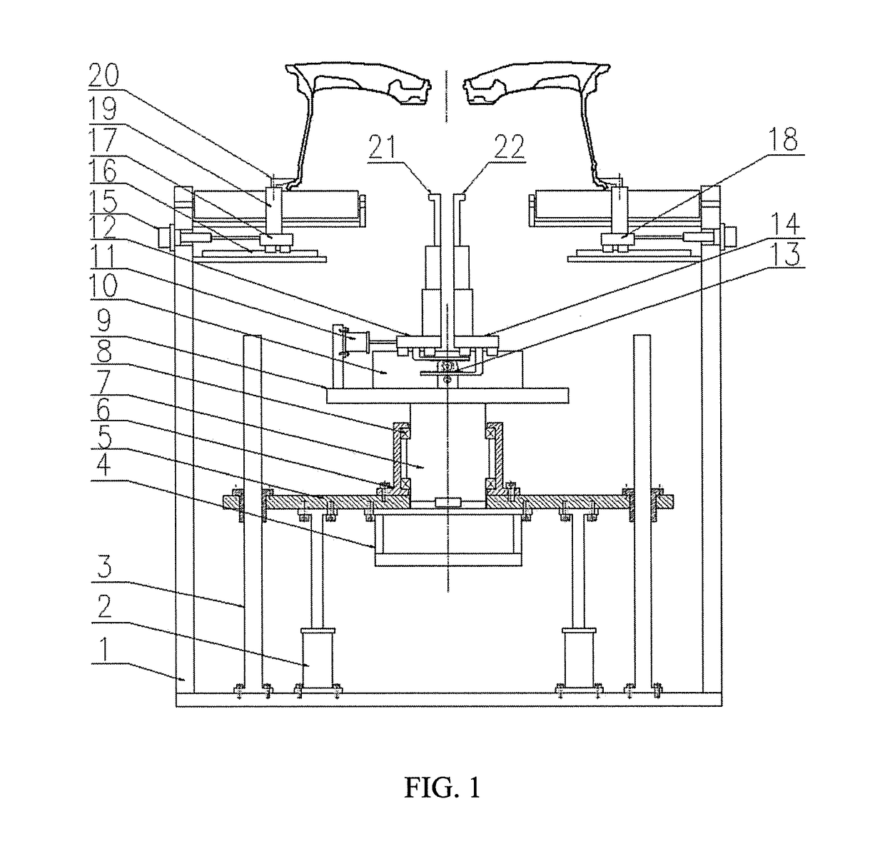
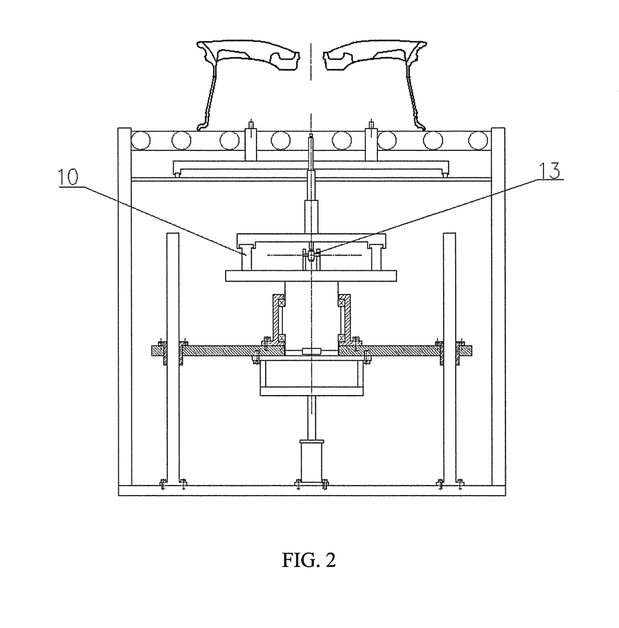
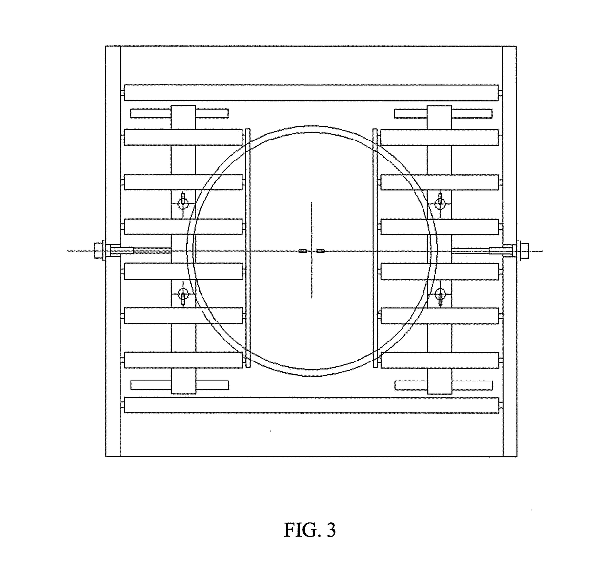
[0019]A high-precision wheel cap section burr removing device includes a frame 1, jacking cylinders 2, guide posts 3, a servo motor 4, a lifting table 5, a bearing seat 6, a shaft 7, a bearing 8, a rotating table 9, adjusting guide rails 10, an adjusting cylinder 11, a left sliding table 12, a gear rack 13, a right sliding table 14, pre-positioning cylinders 15, pre-positioning guide rails 16, a sliding plate I 17, a sliding plate II 18, pre-positioning posts 19, corner cylinder pressure claws 20, a left burr cutter 21 and a right burr cutter 22.

[0020]The four pre-positioning guide rails 16 are symmetrically mounted on the frame 1, and the sliding plate I 17 and the sliding plate II 18 are respectively mounted on the pre-positioning guide rails 16 and driven by the pre-positioning cylinders 15. Two pre-positioning posts 19 ar...


PUM

PropertyMeasurementUnit
distanceaaaaaaaaaa
diameteraaaaaaaaaa
distanceaaaaaaaaaa

Abstract

Disclosed is a high-precision wheel cap section burr removing device, including a frame, jacking cylinders, guide posts, a servo motor, a lifting table, a bearing seat, a shaft, a bearing, a rotating table, adjusting guide rails, an adjusting cylinder, a left sliding table, a gear rack, a right sliding table, pre-positioning cylinders, pre-positioning guide rails, a sliding plate I, a sliding plate II, pre-positioning posts, corner cylinder pressure claws, a left burr cutter and a right burr cutter. The precision positioning system and the burr removing cutter system are integrated to reduce the combined error, and the rotating centers of the burr cutters are superposed with the central axes of the cap section burrs to realize high-precision burr removal, thereby effectively solving the problems of deviation and non-uniformity of burr removal at the cap section.

Description

CROSS-REFERENCE TO RELATED APPLICATIONS[0001]This application claims priority to Chinese Patent Application No. 201710635537.9, filed on Jul. 31, 2017, which is hereby incorporated by reference in its entirety.TECHNICAL FIELD[0002]The present application relates to the technical field of cleaning of burrs at cap sections of wheels after machining, specifically to a device for automatically removing burrs at a cap section with high precision.BACKGROUND ART[0003]The cap section of an aluminum alloy wheel is a joint area of a casting surface and a machining surface and thus has a ring of burrs. The traditional burr removing method is relatively low in positioning precision and poor in consistency of removal of burrs at the cap section edge, and has a phenomenon of non-uniformity, i.e., the removal quantity may be too large on one side of the cap section edge and too small on the other side. Due to low precision when the burrs are removed, chamfers at the cap section edge are not unifor...

Claims


Application Information

Patent Timeline
Patent Type & Authority Applications(United States)
IPC IPC(8): B23D79/12B23B51/10B22D11/126B23Q5/40
CPCB23D79/12B23B51/101B22D11/126B23Q5/40B23B2220/08B23D79/00B23B5/28B23B2215/08
Inventor LIU, HUIYINGLIU, XIAOWEI, GUANGCAI
Owner CITIC DICASTAL
Why Eureka
Eureka Blog
Learn More