Apparatus for isolating a network protector in an electric power distribution network

a technology for electric power distribution networks and protective devices, applied in electrical apparatus, connection, coupling device connections, etc., can solve the problems of damage to the network, and the destruction of the forced paralleling of out of phase feeder system components, so as to improve customer service and satisfaction as well as worker safety, reduce the time required, and the effect of greater safety

Active Publication Date: 2019-01-24
ELECTRICAL MATERIALS
View PDF0 Cites 3 Cited by
  • Summary
  • Abstract
  • Description
  • Claims
  • Application Information

AI Technical Summary

Benefits of technology

[0016]Accordingly, it is an object of the present invention to improve reliability and safety while providing electric power via a grid network incorporating multiple transformer-based network centers.
[0019]A further object of the present invention is to improve customer service and satisfaction as well as worker safety in terms of a utility-based electric power distribution network.
[0020]A still further object of the present invention is to reduce the time required for servicing or replacing a locked-up, or otherwise faulty, network protector device in an electric power distribution network with greater safety and load free interruption-free customer service.
[0021]Still another object of the present invention is to provide voltage overload protection and back-up emergency tripping of network load carrying contactors for improved safety including illuminated optical means for indicating status of bypass contactor in locked-up condition in a network protector device in an electric power distribution power network.
[0022]Still another object of the present invention is to provide a portable, remote controlled system for quickly and safely isolating a network protector device in an electric power distribution network.

Problems solved by technology

Differences in phase angle between the operating voltages of the network feeder cables can result in damage to the network.
In extreme cases even result in the destruction of the forced paralleling of out of phase feeders system components.
Out of phase angle conditions also pose a very dangerous situation for workers who maintain the network.
Network protectors are subject to malfunction or a lock-up condition during operation which permits the load current to flow in the opposite direction from the flow direction in normal operation, so as to direct the current flow from the low voltage secondary side to the high voltage primary side resulting in a highly dangerous condition in the networked group of high voltage network feeder lines.
(1) Interrupting all power served by the single network center resulting in a shutdown of electric service to all customers served from that vault.
This presents a difficult situation for customers, particularly in large buildings having elevator systems with elevators stranded between floors.
In addition, the three network transformer protector clearing approaches discussed above have been the subject of OSHA complaints relating to the unsafe conditions to which workers are exposed in isolating a faulty network protector.
Single phase load dropping can also be precarious with possible arcing associated with load interruption on three phase ever-changing load levels.
While less dangerous than the 3 phase isolation of a network protector, the single phase approach is also dangerous because of the lengthy time lag associated with completion of de-energizing of all the phases.
The time required to control load flow with primary voltage regulation in a substation having as many as four primary network feeder sources can result in excessive heating of the various electric components, including the load carrying cables, resulting in damage to, or destruction of, exposed network components.
These conditions are particularly dangerous in close proximity to a live malfunctioning network protector.

Method used


Image

  • Apparatus for isolating a network protector in an electric power distribution network
  • Apparatus for isolating a network protector in an electric power distribution network
  • Apparatus for isolating a network protector in an electric power distribution network

Examples


Embodiment Construction

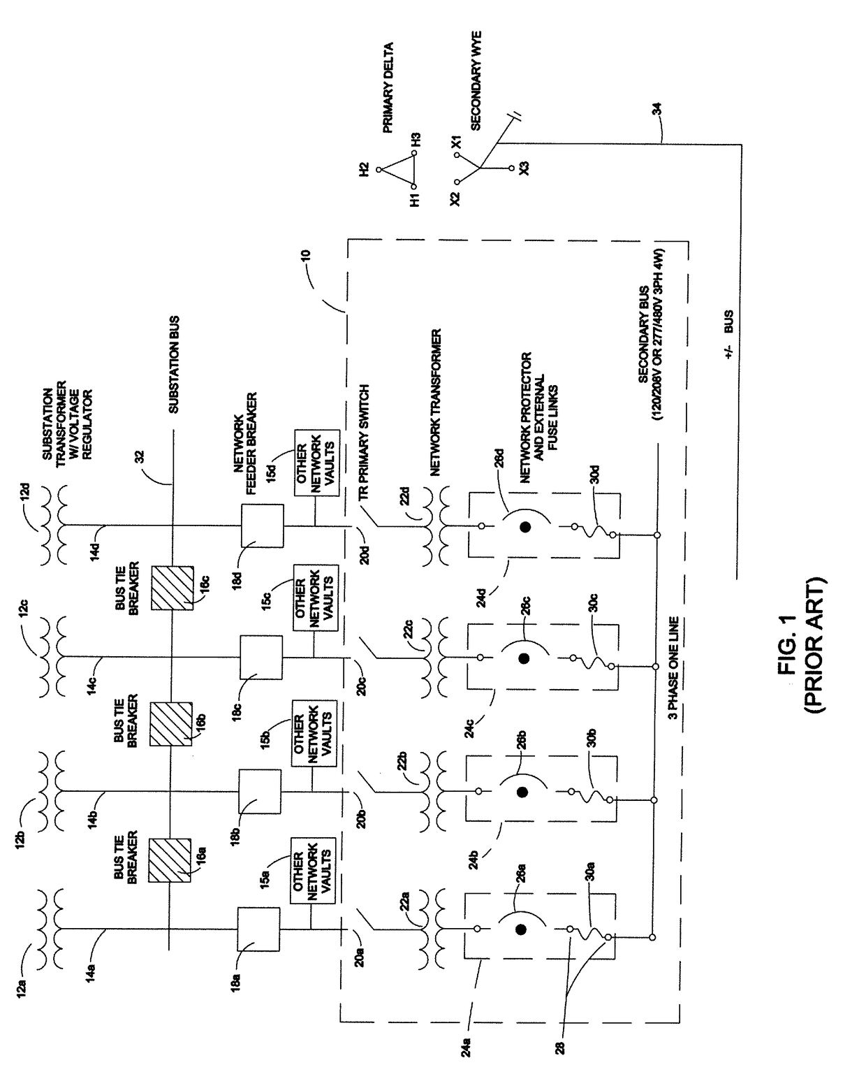
[0030]FIG. 1 is shown a combined schematic and block diagram of the portion of a conventional electrical power distribution network transformer disposed within a network vault 10 in a conventional electrical power distribution network. Network vault 10 includes four paralleled transformers 22a-22d each coupled to a respective network energized secondary bus. The substation transformers with voltage regulators 12a-12d for the network maintain the input voltage provided to the network 10 so as to match the primary voltage supplied by each networked substation transformer 12a-12d. The substation 10 transformers bus further includes three normally open bus tie breakers 16a, 16b and 16c connected between each adjacent pair of network cables 14a-14d, and further coupled to a substation bus 32. Also connected to respective network cables 14a-14d are four network feeder breakers 18a-18d. Other network vaults 15a-15d are coupled to each of the four network cables 14a-14d at the output of eac...


PUM


Abstract

In an electric power distribution network power is provided via high voltage cables carrying large secondary distribution currents which are connected to various electrical components such as transformers and network protectors which detect and accommodate secondary network power flow and problems such as network component malfunctioning or failure, and dangerous operating conditions such as an out of phase current status within the three or four high voltage primary power conducting cables arranged in parallel to share the load. network protectors address, among other things, a voltage out of phase situation in the cables which can lead to dangerous interruption conditions and result in damage to, or destruction of, the power distribution network and safety to the general public. The present invention addresses the problems associated with a faulty or failed network protector which permits continuous reversal in the direction of power (current) flow. Isolation of the problem network protector is achieved by transferring its load to associated network protectors on the secondary network to allow for safe servicing, or removal and replacement, of the hung-up network protector. The inventive electric network protector protection system automatically accommodates either 120 volt or 277 volt network systems, and further contemplates an arrangement for safely and securely connecting the network protector isolator's bus bar to a temporary power cable connected to contactors which can isolate a defective network protector from its associated network transformer.

Description

FIELD OF THE INVENTION[0001]This invention relates generally to electric power distribution networks, and is particularly directed to the isolation of a network protector from the network to permit the safe clearing (interrupting reverse load current flow) of a malfunctioning network protector in the event the malfunctioning network protector is stuck on backfeed.BACKGROUND OF THE INVENTION[0002]The typical electrical power distribution underground network is in the form of a grid having multiple network vaults, commonly referred to as network centers, connected together on the secondary, or customer, side of the network transformers to provide service for multiple customer loads. The system's primary side is connected to source of electrical power which is typically from electric utility substation and includes multiple network transformers in a vault fed from separate primary feeders connected in parallel on the secondary side. The substations are connected via primary network fee...

Claims


Application Information

Patent Timeline
Patent Type & Authority Applications(United States)
IPC IPC(8): H02H7/26H01R13/207
CPCH02H7/26H01R13/207H01R13/213
Inventor O'REGAN, TIMOTHY M.O'REGAN, TIMOTHY J.
Owner ELECTRICAL MATERIALS
Why Eureka
Try Eureka