Cleaning tool
a cleaning tool and cleaning technology, applied in the field of cleaning tools, can solve the problems of high production cost, inconvenient carrying, and high degree of security risk of cleaning tools, and achieve the effects of reducing the risk of wounding, convenient carrying, and simple structur
- Summary
- Abstract
- Description
- Claims
- Application Information
AI Technical Summary
Benefits of technology
Problems solved by technology
Method used
Image
Examples
embodiment 1
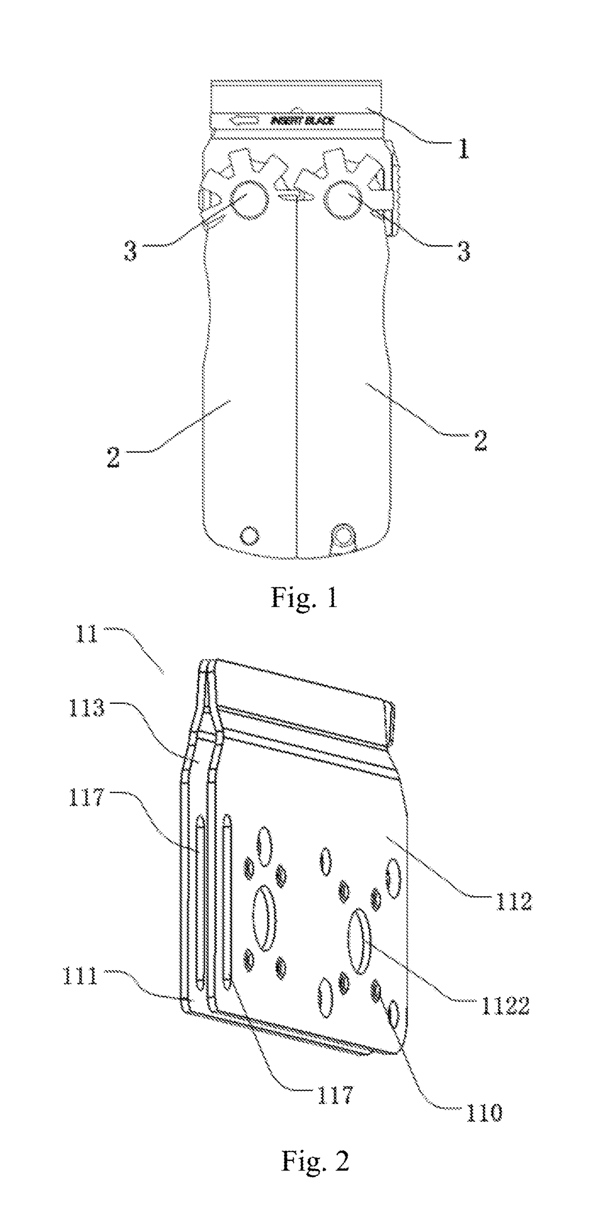
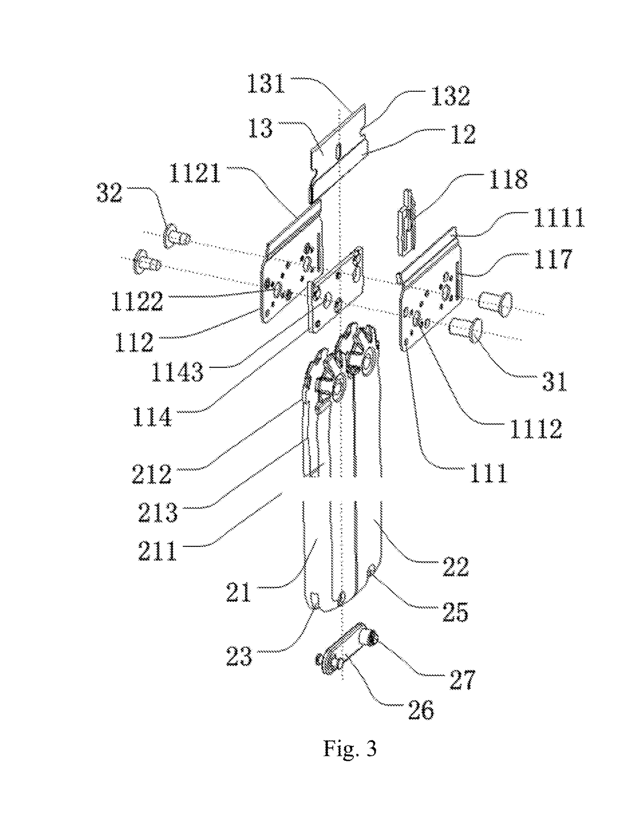
[0069]As shown in FIGS. 1 to 3, this embodiment provides a cleaning tool including a tool head device 1 and a handle portion 2. The tool head device 1 includes a cutting edge 131; and the handle portion 2 is rotatably connected to the tool head device 1; the cutting edge 131 is exposed outside of the handle portion 2 in the use state; and the cutting edge 131 is entirely or partially covered by the handle portion 2 in the non-use state.
[0070]The tool head device 1 includes a tool post 11, a blade holder 12 and a blade 13, the blade holder 12 is detachably fitted to the tool post 11; and the blade 13 is fixed to the blade holder 12; the blade 13 includes a cutting edge 131.
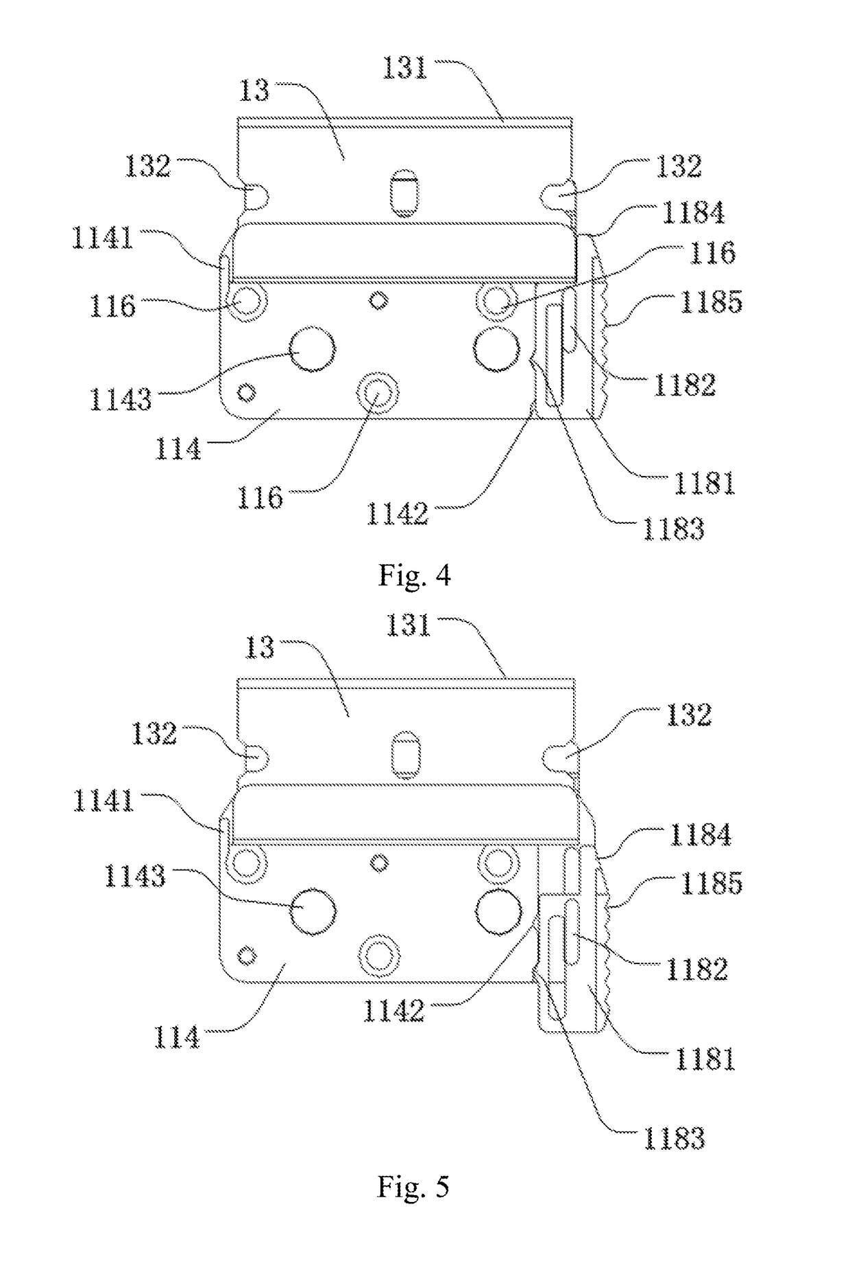
[0071]The tool post 11 includes two oppositely disposed clips, which are respectively a first clip 111 and a second clip 112, the tool post 11 further includes a clip gap 113 and a spacer 114, the second clip 112 and the first clip 111 are connected with each other; and the clip gap 113 is formed between the first ...
embodiment 2
[0089]As shown in FIG. 11, the technical features of Embodiment 2 are largely the same as those of Embodiment 1, and the distinguishing technical feature between them is in that the locking member is not included in Embodiment 2, but the toggleable flap 41 and the clip opening 42 are included therein. The toggleable flap 41 protrudes from the edge of one end of one curved sheet 1111 / 1121 and is snapped into the blade latch recess 132; and the clip opening 42 is formed between the toggleable flap 41 and the curved sheet 1111 / 1121.
[0090]In this embodiment, the toggleable flap 41 protrudes from the edge of one side of the first curved sheet 1111; and the clip opening 42 is formed between the toggleable flap 41 and the first clip 111. The toggleable flap 41 is snapped into the blade latch recess 132 to ensure that the blade 13 will not slide off therefrom; a bending flap 115 is provided at the edge of the other side of the first curved sheet 1111 or the second curved sheet 1121 to ensur...
embodiment 3
[0093]As shown in FIG. 12, the technical features of Embodiment 3 are largely the same as those of Embodiment 1, and the distinguishing technical feature between them is in that the locking member 118 is not included in Embodiment 3, but the following scheme is included therein.
[0094]The blade 13 includes a blade groove 133 which is recessed from the surface of one side of the blade 13; in other embodiments, the blade 13 may further include a blade throughhole penetrating through the middle portion of the blade 13.
[0095]The tool post 11 includes a tool post latch block 51 which is detachably snapped into the blade groove 133 or the blade throughhole; the tool post latch block 51 protrudes from the surface of the first curved sheet 1111 and faces toward the second curved sheet 1121. In other embodiments, the tool post 11 may further include two tool post latch blocks 51, one tool post latch block 51 protrudes from the surface of the first curved sheet 1111 and faces toward the second...
PUM
 Abstract
Description
Claims
Application Information
 - R&D
- Intellectual Property
- Life Sciences
- Materials
- Tech Scout
- Unparalleled Data Quality
- Higher Quality Content
- 60% Fewer Hallucinations
Browse by: Latest US Patents, China's latest patents, Technical Efficacy Thesaurus, Application Domain, Technology Topic, Popular Technical Reports.
© 2025 PatSnap. All rights reserved.Legal|Privacy policy|Modern Slavery Act Transparency Statement|Sitemap|About US| Contact US: help@patsnap.com


