Method and imaging apparatus for optimizing a signal-to-noise ratio of a magnetic resonance image

a magnetic resonance image and signal-to-noise ratio technology, applied in the direction of diagnostic recording/measuring, measurement using nmr, instruments, etc., can solve the problems of long measurement time, shortening measurement time, and changing contrast, so as to increase the signal-to-noise ratio, prolong the measurement time, and improve the effect of snr

Active Publication Date: 2019-01-10
SIEMENS HEATHCARE GMBH
View PDF0 Cites 3 Cited by
  • Summary
  • Abstract
  • Description
  • Claims
  • Application Information

AI Technical Summary

Benefits of technology

The present invention provides a method for operating a magnetic resonance apparatus that increases the signal-to-noise ratio (SNR) in specific regions of interest without extending the measurement time or sacrificing resolution. By adjusting the flip angle and the function f(α) that describes how the RF pulse affects the nuclear spins, the SNR can be optimized over the entire measurement volume. This results in a minimum measure of SNR in the regions of interest, improving visualization and facilitating diagnosis. The method can be easily adjusted for different measurement protocols, and a graphical selection option makes it easy for users to select the desired region of the object for examination.

Problems solved by technology

This does, however, result in a longer measurement time.
This also leads to a lengthening of the measurement time and, in addition, to changes in contrast.
It is also conceivable to increase the basic magnetic field that is applied, though this results in higher costs for operating the magnetic resonance system.
In an acquisition of MR images or of an MR dataset during a magnetic resonance measurement, the problem thus exists if the SNR is increased overall of the regions from which MR data are acquired, that the measurement time is extended and, as a result, data from some regions are acquired with an overfulfilled SNR.

Method used


Image

  • Method and imaging apparatus for optimizing a signal-to-noise ratio of a magnetic resonance image
  • Method and imaging apparatus for optimizing a signal-to-noise ratio of a magnetic resonance image
  • Method and imaging apparatus for optimizing a signal-to-noise ratio of a magnetic resonance image

Examples


Embodiment Construction

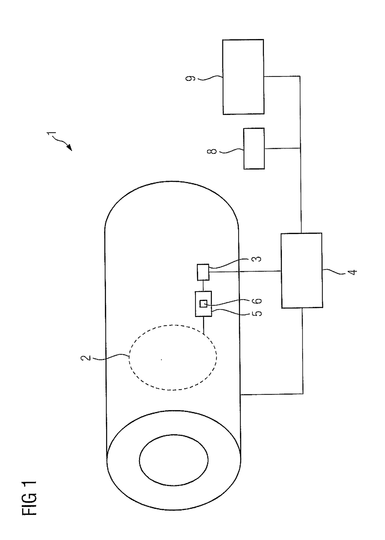
[0043]FIG. 1 shows a magnetic resonance apparatus having a scanner 1 with at least one RF coil 2 that serves at least for transmission of RF signals, but that may also receive RF signals. The RF coil 2 is connected to the control computer 4 of the magnetic resonance apparatus via a terminal 3 that enables an electrical connection. The terminal 3 may be a plug-and-socket connection. The terminal 3 enables different RF coils 2 to be connected to the control computer 4. FIG. 1 is obviously a simplified representation, since there are generally more components than just the terminal 3 disposed between the RF coil 2 and the control computer 4 of the magnetic resonance apparatus.

[0044]The RF coil 2 has an information medium 5 that carries an information code 6 serving as a coil identification code. For example, the identification code 6 can be a numerical sequence, such as the digits 124, which e.g. stand for a specific head coil.

[0045]A display device 8 and an input device 9 are also con...


PUM


Abstract

In a method and apparatus for optimizing the signal-to-noise ratio (SNR) of a magnetic resonance (MR) dataset acquired by means of a magnetic resonance system having at least one transmit coil, a measurement protocol for an acquisition that is to be performed in order to obtain the MR dataset of a predefined measurement volume. A deviation of an actual flip angle from the predefined flip angle in a specific area of the predefined measurement volume is determined for a preset transmitter scaling. The transmitter scaling of the RF pulse is adjusted in order to correct the actual flip angle so that the actual flip angle is approximated to the predefined flip angle in the specific area. The MR dataset is acquired with the adjusted transmitter scaling.

Description

BACKGROUND OF THE INVENTIONField of the Invention[0001]In the course of a magnetic resonance (MR) examination, a patient is positioned on a patient table, the local radio-frequency (RF) coil that is preferred for the examination, e.g. a knee coil or a head coil, is connected to the magnetic resonance scanner. Thereafter the patient is advanced into the tunnel of the magnetic resonance scanner. Adjustment measurements are thereupon carried out, inter alia, in order to accurately determine the resonance frequency and in order to fine-tune the shim coils that are used to compensate inhomogeneities in the basic magnetic field.[0002]Once all preparatory activities have been completed, the actual diagnostic measurements can be performed. Measurement protocols are employed for this purpose. A measurement or scan protocol is a measurement sequence composed of preset parameters, the preset values being adjusted for specific examinations. The local RF coil, or another RF coil such as a whole ...

Claims


Application Information

Patent Timeline
IPC IPC(8): G01R33/56G01R33/54
CPCG01R33/56G01R33/543G01R33/4806G01R33/3854A61B5/055G01R33/586
Inventor FEIWEIER, THORSTENHOELSCHER, UVO
Owner SIEMENS HEATHCARE GMBH
Why Eureka
Try Eureka