
X-ray inspection apparatus and correction method for x-ray inspection apparatus

a technology of x-ray inspection and correction method, which is applied in the direction of instrumentation, material analysis using wave/particle radiation, image data processing, etc., can solve the problem of non-uniform intensity of x-ray incident on each sensor element in the inspection apparatus, and achieve wide transmittance range, accurate acquisition, and high accuracy

Active Publication Date: 2019-01-03
ANRITSU CORP
View PDF36 Cites 10 Cited by
  • Summary
  • Abstract
  • Description
  • Claims
  • Application Information

AI Technical Summary

Benefits of technology

The invention provides an X-ray inspection apparatus and a correction method that can correct image data acquired by multiple X-ray detection sensors. This is achieved by changing the X-ray incidence conditions and acquiring correction data needed to correct the image data for each incidence condition. The apparatus can accurately acquire image data within a wide range of transparency caused by the passing of an inspected article and can correctly determine foreign objects. The correction data can be read from a memory and used for automatically correcting the image data. The technical effect of the invention is to improve the accuracy of X-ray inspection and enable the detection and correction of foreign objects and other inspection targets.

Problems solved by technology

In addition to a change in transmittance caused by the presence of foreign object intrusion, the presence of a damaged or missing ingredient, and the like in the inspected article, a difference in distance to each X-ray sensor element from the X-ray source due to the spreading emission of the X-ray toward an inspection region makes the intensity of the X-ray incident on each sensor element non-uniform in the article inspection apparatus that uses the X-ray.

Method used


Image

  • X-ray inspection apparatus and correction method for x-ray inspection apparatus
  • X-ray inspection apparatus and correction method for x-ray inspection apparatus
  • X-ray inspection apparatus and correction method for x-ray inspection apparatus

Examples


Embodiment Construction

[0039]Hereinafter, an embodiment of the invention will be described based on the drawings.

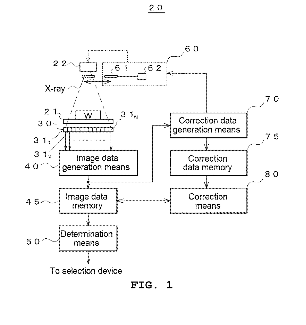
[0040]FIG. 1 illustrates a configuration of an article inspection apparatus 20 to which the invention is applied.

[0041]The article inspection apparatus 20 includes, as basic constituents, a transport device 21, an X-ray generation source 22, X-ray detection means 30, image data generation means 40, an image data memory 45, and determination means 50. First, these basic constituents will be described.

[0042]The transport device 21 transports an inspected article W in a predetermined direction (a direction orthogonal to the page of FIG. 1) in order to cause the inspected article W to pass through a predetermined inspection region. While a transport device such as a conveyor that horizontally transports the inspected article W at a constant speed is generally used, the transport device does not need to include a motive power source. The inspected article may be slid on a slope or may be dropped fro...


PUM

PropertyMeasurementUnit
transmittanceaaaaaaaaaa
widthaaaaaaaaaa
widthaaaaaaaaaa

Abstract

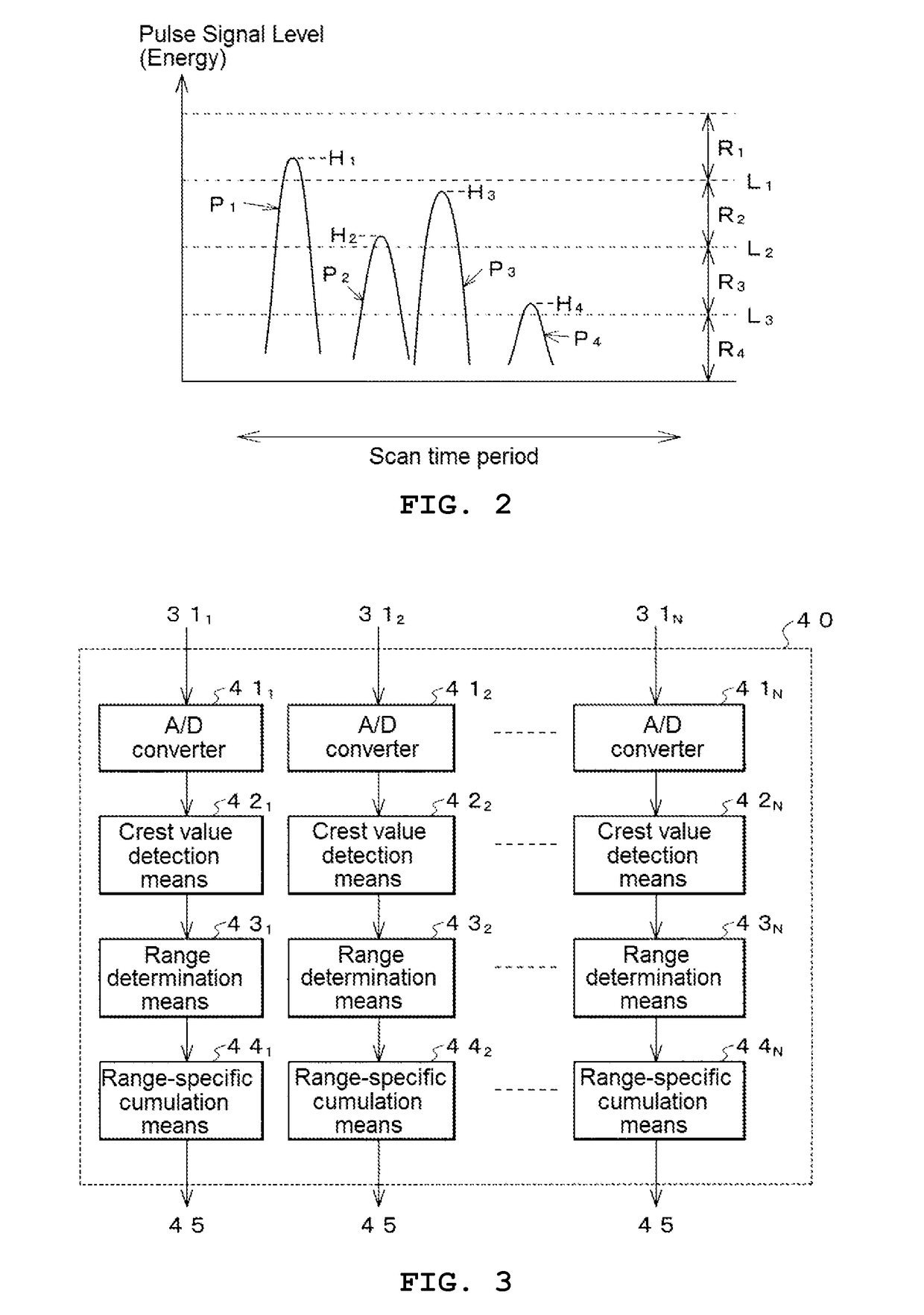
To correctly acquire image data of an inspected article by preventing a difference in shade between images caused by a difference in position or sensitivity between sensor elements. An X-ray generation source irradiates an inspection region where an inspected article passes with an X-ray. X-ray detection means receives the X-ray passing through the inspection region using a plurality of sensor elements. Image data generation means generates image data of the inspected article from an output of the X-ray detection means. Incidence condition changing means changes two or more kinds of X-ray incidence conditions common for all of the sensor elements of the X-ray detection means in a state of absence of the inspected article in the inspection region. Correction data generation means acquires correction data that is needed for making a shade of an image uniform for each incidence condition.

Description

TECHNICAL FIELD[0001]The present invention relates to a technology for improving the inspection accuracy of an article inspection apparatus that checks the presence of a defect such as foreign object intrusion and a missing ingredient in a product such as food.BACKGROUND ART[0002]In a factory where food and the like are produced, a product is automatically inspected during its transport by a conveyor or the like using an article inspection apparatus for checking the presence of a defect such as foreign object intrusion and a missing ingredient in the product, and the product is categorized as a normal product or a defective product.[0003]Particularly, a product such as food needs to be closely inspected for the presence of an intruding foreign object such as metal or plastic. Therefore, an article inspection apparatus that uses an X-ray has been developed in recent years.[0004]Generally, in the article inspection apparatus that uses an X-ray, an X-ray that has a width in a direction...

Claims


Application Information

Patent Timeline
Patent Type & Authority Applications(United States)
IPC IPC(8): G01N23/04G06T7/00
CPCG01N23/04G06T7/0008G01N2223/401G01N2223/313G01N2223/32G01N2223/3308G01N2223/643G01N2223/652G01N23/06G01N23/18G01N23/087G01N23/083G01N23/10G01N23/046G01N23/043
Inventor MIYAZAKI, ITARUTANAKA, AKIHIROKANAI, TAKASHIHAYASHI, HISASHI
Owner ANRITSU CORP
Learn More