
Lightning protection system and associated nose

a protection system and shielding technology, applied in the direction of electrical equipment, antennas, movable body antenna adaptation, etc., can solve the problems of affecting the flow of air around the nose, affecting the safety of passengers, and destroying the electromagnetic transparency around the antenna, so as to increase the aerodynamic drag, reduce the aerodynamic drag, and increase the fuel consumption of the aircraft

Active Publication Date: 2018-12-20
DASSAULT AVIATION
View PDF6 Cites 0 Cited by
  • Summary
  • Abstract
  • Description
  • Claims
  • Application Information

AI Technical Summary

Benefits of technology

The invention aims to provide a lightning protection system for aircraft that reduces the aerodynamic drag and improves the aesthetics while ensuring good transparency to electromagnetic waves. The current lightning protection systems disrupt the flow of air around the nose and increase fuel consumption of the aircraft due to aerodynamic drag.

Problems solved by technology

However, such a system is not fully satisfactory.
Indeed, the metal bar damages the electromagnetic transparency around the antenna.
Furthermore, the nose being arranged at the front of the aircraft and having an aerodynamic profile, the known lightning protection systems disrupt the flow of air around the nose and increase the aerodynamic drag.
The lightning protection system then increases the fuel consumption of the aircraft.

Method used


Image

  • Lightning protection system and associated nose
  • Lightning protection system and associated nose
  • Lightning protection system and associated nose

Examples


first embodiment

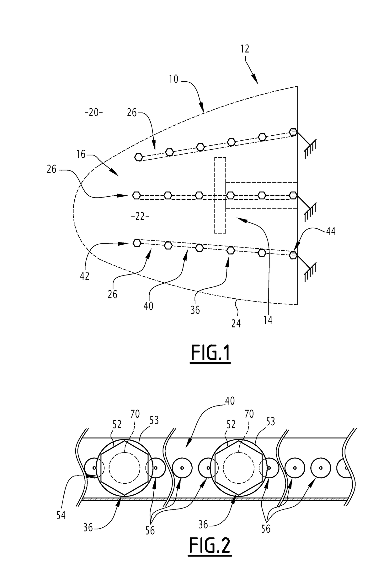
[0108]The operation of the nose 10 will now be described.

[0109]When a lightning bolt forms in the mass of air 20 surrounding the aircraft 12, the latter is attracted by at least one of the lightning traps 36 and touches the lightning trap 36.

[0110]An electric current is generated in the lightning trap 36 touched by the lightning bolt.

[0111]The electric current is guided through the lightning trap 36 from the outer surface 34 of the wall 24 toward the inner surface 32. In particular, the electric current is guided from the frustoconical upper part 46 of the lightning trap 36 toward its lower part 48.

[0112]The washer 53 of the nut 52 of the lightning trap 36 being electrically conductive and in contact with a first pellet 56, the current passes from the lightning trap 36 to said first pellet 56.

[0113]Subsequently, from this first pellet 56, the electric current passes in the row 26 of pellets by successive ionization of the fluid separating two successive pellets.

[0114]The electric c...

second embodiment

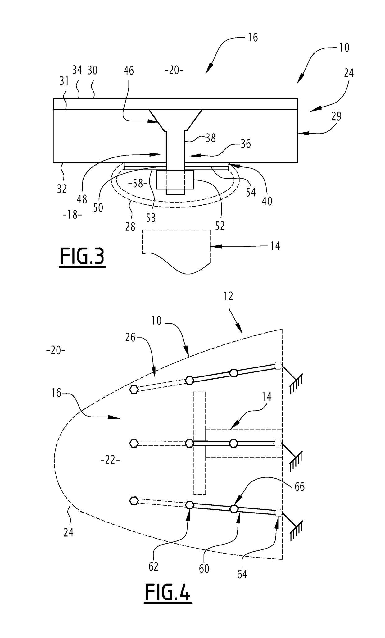
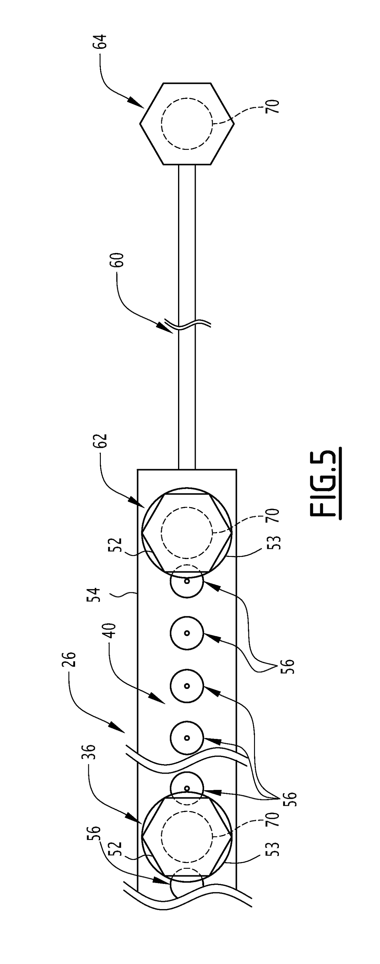
[0128]In this second embodiment, each row 26 of pellets further comprises an electrically conductive metal foil 60, for example fixed on the inner surface 32 of the wall 24 and in contact with this inner surface 32.

[0129]The conductive metal foil 60 has a constant square, rectangular or circular cross-section.

[0130]Alternatively, the section is not constant over the entire conductive metal foil 60. The section is for example circular between the lightning traps 36 and flat at the lightning traps 36.

[0131]The conductive metal foil 60 is fixed on the inner surface 32, at a front end, by an intermediate lightning trap 62 fixing both said conductive metal foil 60 and the strip with pellets 40 of the row 26 of pellets.

[0132]The conductive metal foil 60 is fixed on the inner surface 32, at a rear end, by a rear lightning trap 64. The rear lightning trap 64 is connected to a primary metal structure of the aircraft, for airplane grounding formed by the primary metal structure of the aircraf...


PUM


Abstract

A lightning protection system of an aircraft includes a wall defining an inner surface and an outer surface. The outer surface is configured to come into contact with a mass of air located around the aircraft. The lighting protection system also includes at least two electrically conductive lighting traps received in holes traversing the wall and at least one strip with pellets having an electrically insulating substrate and electrically conductive pellets spaced apart from one another on the electrically insulating substrate. The strip with pellets is fastened on the wall by the two lightning traps. The strip with pellets is attached on the inner surface of the wall.

Description

[0001]The present invention relates to a lightning protection system of an aircraft comprising a wall, defining an inner surface and an outer surface, the outer surface being intended to come into contact with a mass of air located around the aircraft; at least two lightning traps, received in holes traversing the wall, the lightning traps being electrically conductive, and at least one strip of pellets spaced apart from one another on the electrically insulating substrate, the strip of pellets being fastened on the wall by the two lightning traps.[0002]Such a lightning protection system is in particular used in the protection of an aircraft nose housing an antenna for emitting or receiving an electromagnetic signal. The antenna and the nose itself are in fact elements sensitive to lightning strikes, which may damage or destroy them. The lightning protection system is able to channel the electrical current generated by the lightning.BACKGROUND[0003]Among the known lightning protecti...

Claims


Application Information

Patent Timeline
Patent Type & Authority Applications(United States)
IPC IPC(8): B64D45/02H01Q1/28B64C1/36
CPCB64D45/02H01Q1/281H01Q1/286B64C1/36H02G13/80
Inventor TRISTANT, FABRICE
Owner DASSAULT AVIATION
Learn More