
Composite electronic component, composite electronic component package, circuit board, and method of producing a composite electronic component

a technology of electronic components and composite electronic components, which is applied in the direction of capacitor manufacturing, sustainable manufacturing/processing, and final product manufacturing, can solve the problems of increasing production costs, and achieve the effect of saving mount space and production costs

Active Publication Date: 2018-12-06
TAIYO YUDEN KK
View PDF5 Cites 0 Cited by
  • Summary
  • Abstract
  • Description
  • Claims
  • Application Information

AI Technical Summary

Benefits of technology

The patent text explains that the current design of a composite electronic component leads to increased production costs due to the need for additional external electrodes to connect the resistive element to the circuit board, as well as increased mount space requirements due to the height of the resistive element. The patent aims to provide a solution that saves mount space and produces a cost-effective composite electronic component.

Problems solved by technology

This increases a production cost.

Method used


Image

  • Composite electronic component, composite electronic component package, circuit board, and method of producing a composite electronic component
  • Composite electronic component, composite electronic component package, circuit board, and method of producing a composite electronic component
  • Composite electronic component, composite electronic component package, circuit board, and method of producing a composite electronic component

Examples


Embodiment Construction

[0062]Hereinafter, embodiments of the present invention will be described with reference to the drawings.

[0063]In the figures, an X axis, a Y axis, and a Z axis orthogonal to one another are shown as appropriate. The X axis, the Y axis, and the Z axis are common in all figures.

1. Composite Electronic Component 1

1.1 Overall Configuration

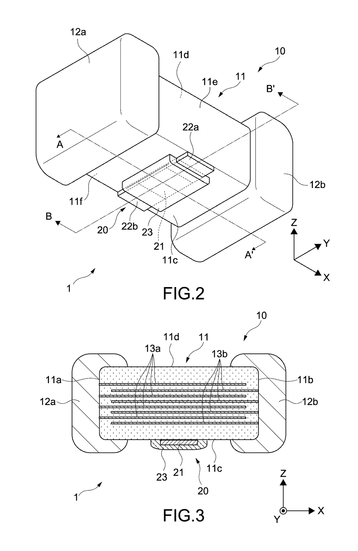
[0064]FIGS. 1 to 4 are views of a composite electronic component 1 according to an embodiment of the present invention. FIG. 1 is a front view of the composite electronic component 1. FIG. 2 is a perspective view of the composite electronic component 1. FIG. 3 is a cross-sectional view of the composite electronic component 1 taken along the A-A′ line in FIG. 2. FIG. 4 is a cross-sectional view of the composite electronic component 1 taken along the B-B′ line in FIG. 2.

[0065]The composite electronic component 1 includes two electronic components in combination. Specifically, the composite electronic component 1 includes a multi-layer ceramic capacitor ...


PUM

PropertyMeasurementUnit
capacitanceaaaaaaaaaa
lengthaaaaaaaaaa
temperatureaaaaaaaaaa

Abstract

A composite electronic component includes: a first electronic component including a ceramic body having a main surface caused to face a circuit board at a time of mounting and first and second end surfaces orthogonal to the main surface, and a first external electrode and a second external electrode respectively provided to the first end surface and the second end surface and respectively extending from the first end surface and the second end surface to the main surface; and a second electronic component including a functional film provided to the main surface, and a first electrode film and a second electrode film provided to both end portions of the functional film separately from the first external electrode and the second external electrode, the second electronic component being configured to fit within a thickness of each of the first external electrode and the second external electrode from the main surface.

Description

CROSS-REFERENCE TO RELATED APPLICATION[0001]This application claims the benefit under 35 U.S.C. § 119 of Japanese Patent Application No. 2017-111542, filed Jun. 6, 2017, the disclosure of which is herein incorporated by reference in its entirety.BACKGROUND[0002]The present invention relates to a composite electronic component, a composite electronic component package, a circuit board, and a method of producing a composite electronic component.[0003]There is known a circuit board on which a plurality of integrated circuits (ICs) are mounted and which is capable of achieving various functions. Other than the ICs, various components are also mounted on the circuit board. For example, the circuit board includes a passive element such as a capacitor or a resistive element in the vicinity of each IC so as to improve the quality of a signal transmitted and received between the ICs.[0004]For example, in a small circuit board as used in a wearable device, a small component, an embedded compo...

Claims


Application Information

Patent Timeline
Patent Type & Authority Applications(United States)
IPC IPC(8): H01G4/40H01G4/248H01C13/02H01G4/30H01C7/00H05K1/18H01C17/065
CPCH01G4/40H01G4/248H01C13/02H01G4/30H01C7/003H05K1/181H01C17/06566H01G4/232H05K2201/10015H05K2201/10022H05K2201/1053H05K2201/10636H01C1/02H01C1/14H01C1/16H01C13/00H01G4/12H05K1/111H05K3/3431H05K2201/10045H01G2/065Y02P70/50H01G13/00
Inventor AIDA, SHINSASAKI, KENICHI
Owner TAIYO YUDEN KK
Learn More