
Ultrasonic cutting element and ultrasonic treatment tool

a cutting element and ultrasonic technology, applied in piezoelectric/electrostrictive/magnetostrictive devices, medical science, surgery, etc., can solve the problems of inability to obtain sufficient cutting performance and inability to obtain sufficient vibration rate, etc., to achieve stable vibration, confine vibration energy, and small size

Active Publication Date: 2018-12-06
FUJIFILM CORP
View PDF0 Cites 1 Cited by
  • Summary
  • Abstract
  • Description
  • Claims
  • Application Information

AI Technical Summary

Benefits of technology

The ultrasonic cutting element in this patent is a new type of ultrasonic blade that uses flexural vibrators that vibrate in opposite phases, even when smaller than traditional vertical vibrators. This allows for a wider range of frequencies to be used, resulting in stable vibrations even at large amplitudes. The vibration energy is focused, even when a flexible wire is connected, ensuring continued stable vibrations. This new ultrasonic blade is effective while also being small and flexible, making it ideal for use in flexible endoscopes.

Problems solved by technology

However, in the case of using the ultrasonic cutting element described in “Enhancement of Vibration Amplitude of Micro Ultrasonic Scalpel Using PZT Film” by Minoru KUROSAWA et al. in IEICE TECHNICAL REPORT US2009-(2009-), it is not possible to obtain a sufficient vibration rate.
Therefore, there has been a problem in that sufficient cutting performance cannot be obtained.

Method used


Image

  • Ultrasonic cutting element and ultrasonic treatment tool
  • Ultrasonic cutting element and ultrasonic treatment tool
  • Ultrasonic cutting element and ultrasonic treatment tool

Examples


examples

[0082]Hereinafter, the present invention will be described in more detail using examples and comparative examples.

[0083]Structures A to C of small ultrasonic knives of Comparative Example 1, Comparative Example 2, and Example 1, which are specific examples of the ultrasonic cutting element of the present invention, are illustrated in FIG. 8A, FIG. 8B, and FIG. 8C respectively.

[0084]In FIG. 8A, FIG. 8B, and FIG. 8C, the dimensions of individual portions of individual elements are also indicated. A reference sign “t” in the drawings represents the plate thickness of each substrate. All of the plate thicknesses have a unit of [mm].

[0085]In addition, FIG. 9A, FIG. 9B, and FIG. 9C are schematic perspective views illustrating the displacement states of individual vibrators in vibration modes in FIG. 8A, FIG. 8B, and FIG. 8C respectively. In FIG. 9A, FIG. 9B, and FIG. 9C, the color appears lighter as the displacement amount from the standstill state (indicated by a fine solid line) increas...


PUM


Abstract

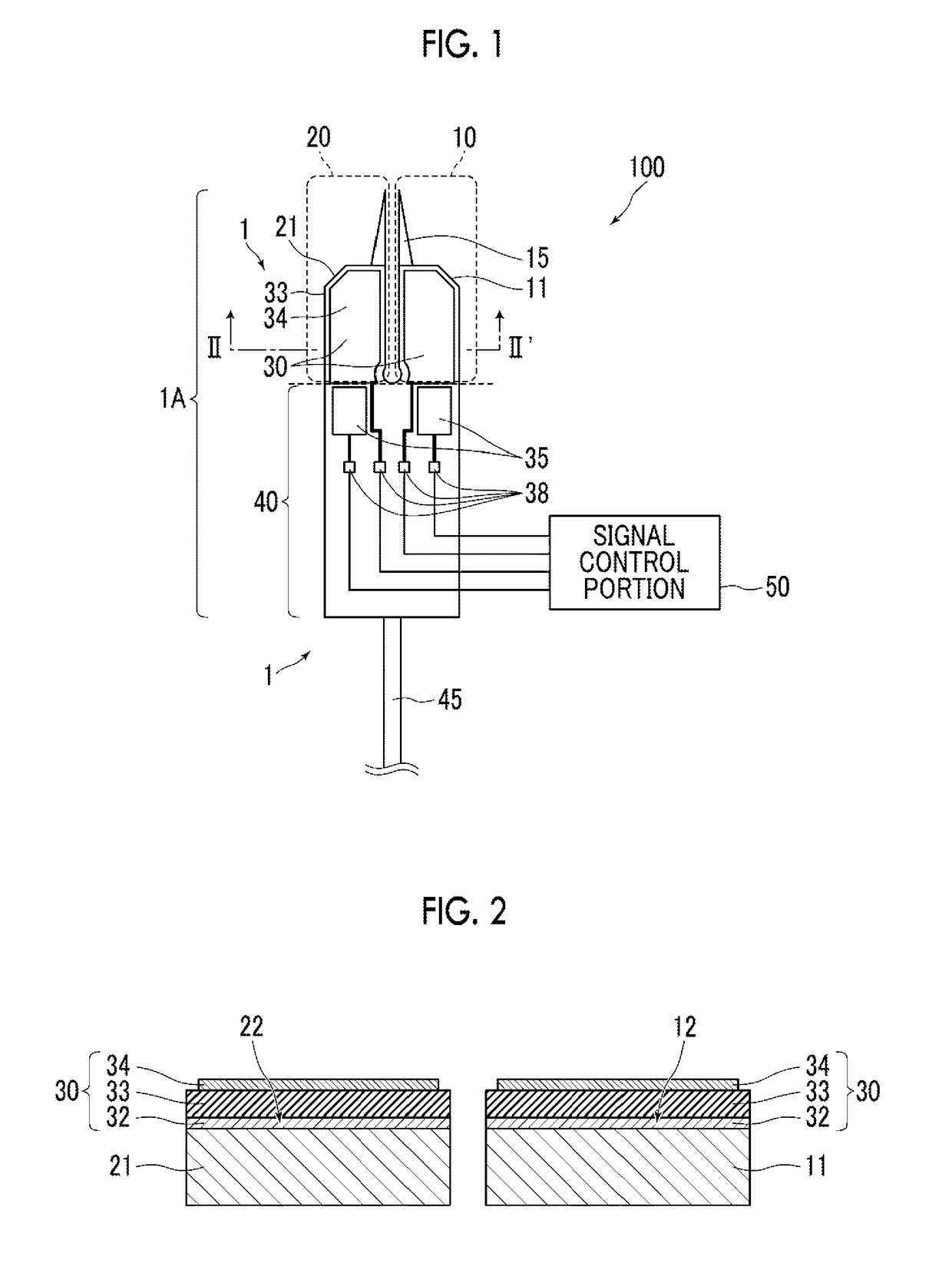
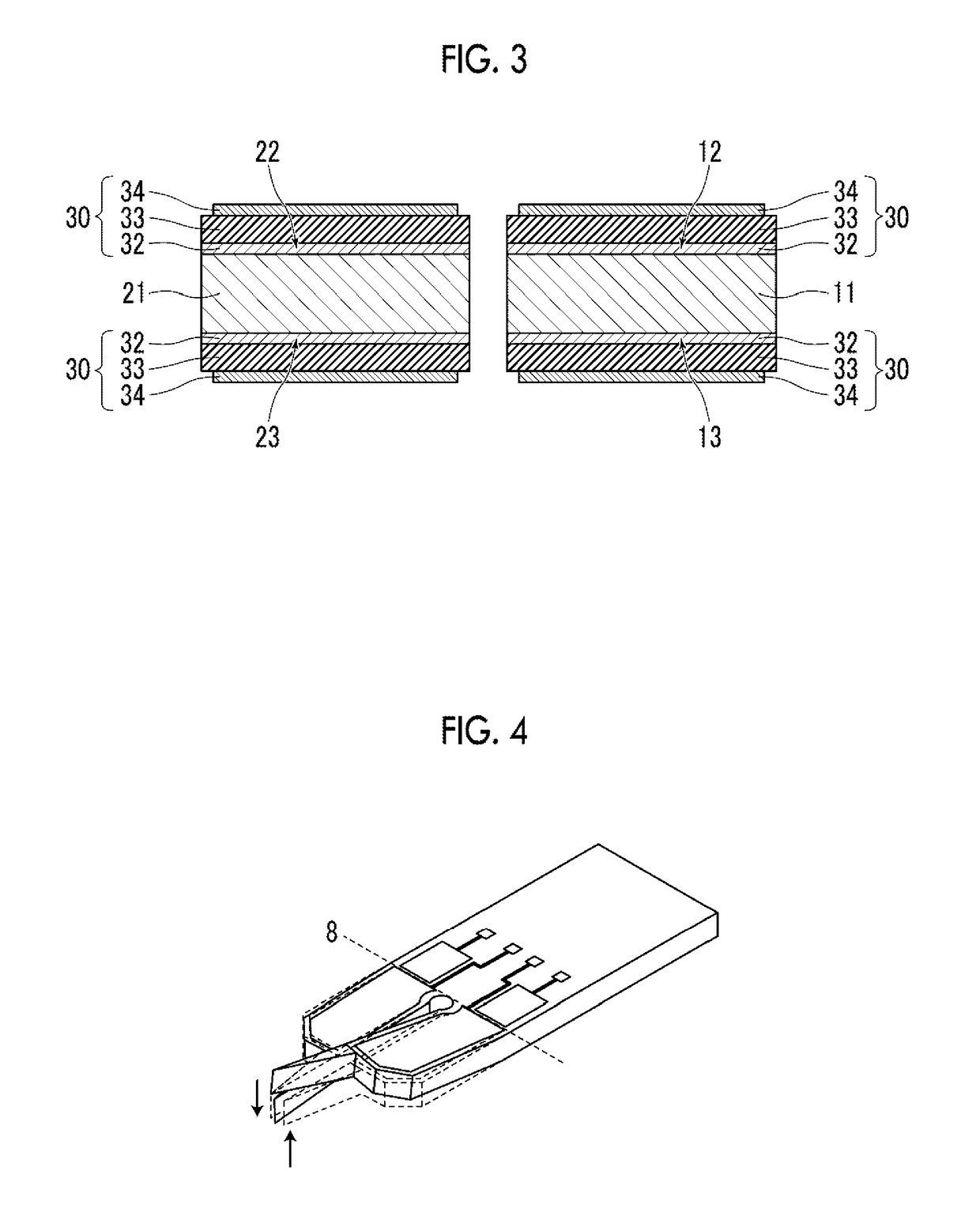
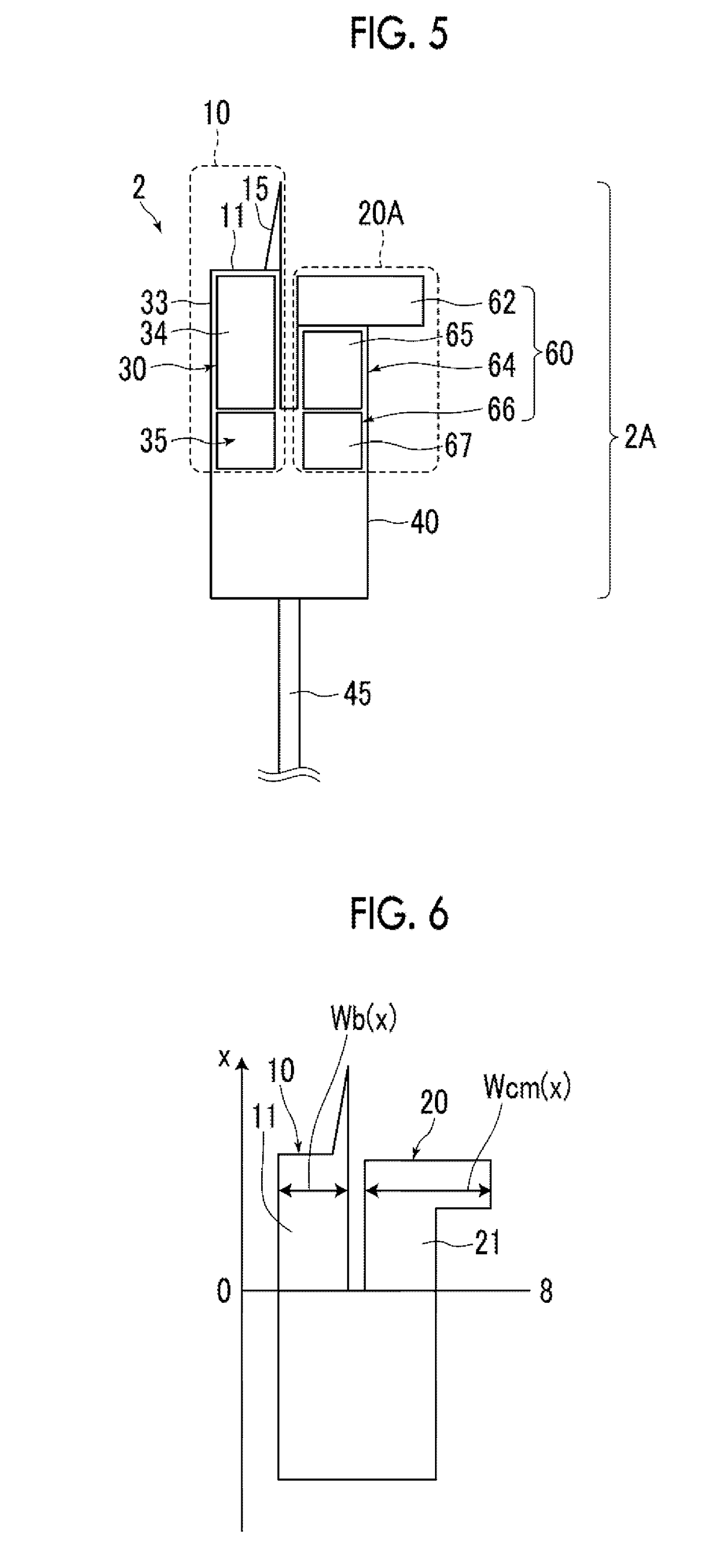
Provided is an ultrasonic cutting element including a blade arm having a primary vibration plate and a blade portion fixed to one end of the primary vibration plate, a counter mass arm including one or more secondary vibration plates, a holding member to which vibration ends of the blade arm and the counter mass arm are respectively connected and which holds the blade arm and the counter mass arm in parallel, and a driving portion being a piezoelectric actuator that imparts ultrasonic vibrations to at least one of the primary vibration plate or the secondary vibration plate, in which the blade arm and the counter mass arm respectively bending-vibrate in a primary surface direction in a resonant mode in which the arms vibrate in mutually opposite phases as flexural vibrators.

Description

CROSS-REFERENCE TO RELATED APPLICATIONS[0001]This application is a continuation application of International Application No. PCT / JP2017 / 007485 filed Feb. 27, 2017, which was published under PCT Article 21(2) in Japanese, and which claims priority under 35 U.S.C. § 119(a) to Japanese Patent Application No. 2016-040614, filed Mar. 3, 2016. The above applications are hereby expressly incorporated by reference, in their entirety, into the present application.BACKGROUND OF THE INVENTION1. Field of the Invention[0002]The present invention relates to an ultrasonic cutting element and an ultrasonic treatment tool which cut subjects by the ultrasonic vibration of a cutting edge and particularly to an ultrasonic cutting element and an ultrasonic treatment tool which have a structure enabling the realization of a size small enough to be stored in a pair of forceps ports in a flexible endoscope.2. Description of the Related Art[0003]Ultrasonic knives that are used as endoscopic treatment tools ...

Claims


Application Information

Patent Timeline
IPC IPC(8): A61B17/32H01L41/08H01L41/314
CPCH01L41/314A61B17/320068A61B17/320016H01L41/081A61B2017/00345A61B2017/00402A61B2017/320075H10N30/2042H10N30/074H10N30/706A61B17/32
Inventor NAONO, TAKAYUKI
Owner FUJIFILM CORP
Learn More