
System and method for reducing attractive forces between a deposition mask and substrate and a deposition system and method utilizing the same

Inactive Publication Date: 2018-11-29
EMAGIN CORP
View PDF0 Cites 7 Cited by
  • Summary
  • Abstract
  • Description
  • Claims
  • Application Information

AI Technical Summary

Benefits of technology

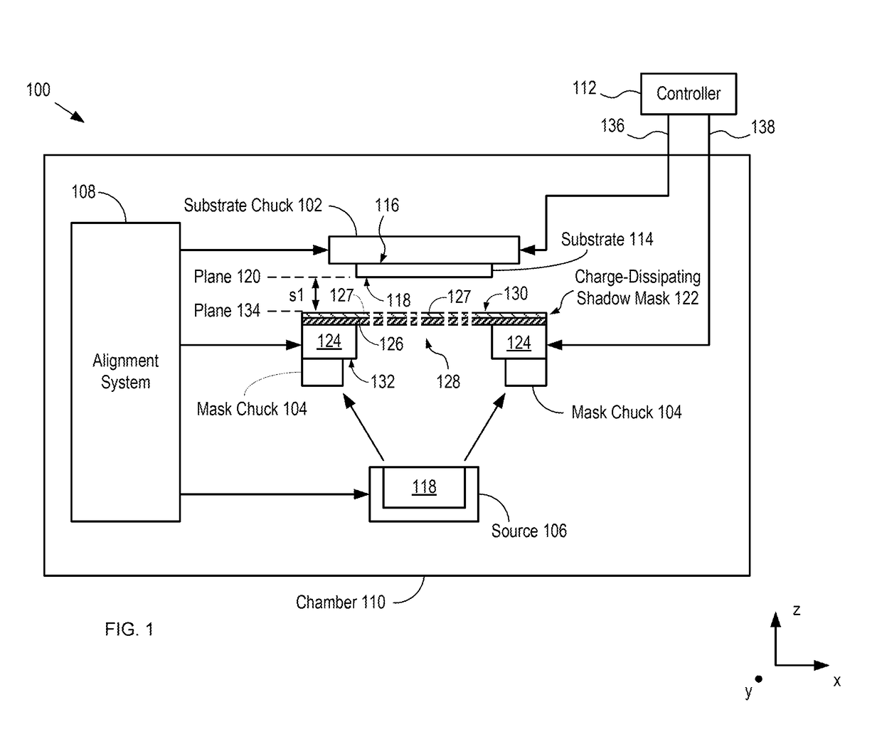
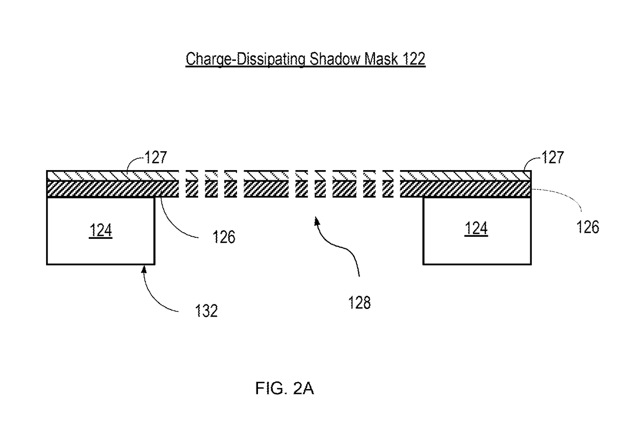
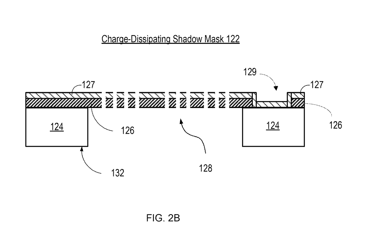
The present invention is about a method for making very precise patterns of material on a substrate using electrostatic chucks and a special mask. The mask has a thin layer of conductive material on its surface which helps to reduce the buildup of charge on the mask, which can cause unwanted effects. With this method, the mask and substrate can be placed very close to each other, resulting in higher resolution and more precise patterns.

Problems solved by technology

Furthermore, many materials, such as organic materials, cannot be subjected to photolithographic chemicals without damaging them, which makes depositing such materials by shadow mask a necessity.
Unfortunately, the feature resolution that can be obtained by conventional shadow-mask deposition is diminished due to the fact that the deposited material tends to spread laterally after passing through the shadow mask—referred to as “feathering.” Feathering increases with the magnitude of the separation between the substrate and the shadow mask.
In conventional use with only a single electrostatic chuck this is not problematic, but as the shadow mask and substrate are moved into extremely close proximity, these charges may attract and result in the shadow mask and substrate sticking together, particularly as each is very flat and rigid.
Depending on the strength of the attractive force between the shadow mask and substrate, this may pose a number of problems.
In mild cases, alignment of the substrate and shadow mask may be impeded by the attractive force between the two objects.
In more severe cases, the shadow mask and substrate may stick together and become nearly impossible to separate.
Both situations are problematic and can lead to significant damage and loss of both materials and time.
In practice, therefore, critical features formed by prior-art shadow-mask-based deposition techniques are typically separated by relatively large areas of open space to accommodate feathering, which limits the device density that can be obtained.
Due to feathering issues, prior-art AMOLED displays have typically been restricted to approximately 600 pixels-per-inch (ppi) or less, which is insufficient for many applications, such as near-to-eye augmented reality and virtual-reality applications.
In addition, the need for large gaps within and between the pixels gives rise to a reduced pixel fill factor, which reduces display brightness.
As a result, the current density through the organic layers must be increased to provide the desired brightness, which can negatively impact display lifetime.

Method used


Image

  • System and method for reducing attractive forces between a deposition mask and substrate and a deposition system and method utilizing the same
  • System and method for reducing attractive forces between a deposition mask and substrate and a deposition system and method utilizing the same
  • System and method for reducing attractive forces between a deposition mask and substrate and a deposition system and method utilizing the same

Examples


Embodiment Construction

[0041]In the following detailed description of various embodiments of the system and method of the present invention, numerous specific details are set forth in order to provide a thorough understanding of various aspects of one or more embodiments. However, the one or more embodiments may be practiced without some or all of these specific details. In other instances, well-known methods, procedures, and / or components have not been described in detail so as not to unnecessarily obscure aspects of embodiments.

[0042]While preferred embodiments are disclosed, still other embodiments of the system and method of the present invention will become apparent to those skilled in the art from the following detailed description, which shows and describes illustrative embodiments. As will be realized, the following disclosure is capable of modifications in various obvious aspects, all without departing from the spirit and scope of the present invention. Also, the reference or non-reference to a p...


PUM

PropertyMeasurementUnit
Electrical conductoraaaaaaaaaa
Electrostatic forceaaaaaaaaaa
Attractive forceaaaaaaaaaa

Abstract

A system and method for reducing attractive forces between a deposition mask and a substrate is provided that enables high-resolution direct deposition of a patterned layer of material on a substrate using electrostatic chucks for holding the substrate and the shadow mask. A charge-dissipating shadow mask is utilized that comprises a thin conductive layer on the surface of the membrane of the shadow mask. The conductive layer helps to dissipate the charge that accumulates on the membrane of the shadow mask, thereby reducing the attractive forces between the substrate and the shadow mask. As a result, the shadow mask and substrate can be placed in closer proximity to each other than would be possible without the charge-dissipating shadow mask, thereby reducing feathering effects and enabling higher resolution direct deposition.

Description

STATEMENT OF RELATED CASES[0001]This application claims priority to U.S. Provisional Application Ser. No. 62 / 510,580, filed May 24, 2017, whose entire disclosure is incorporated herein by reference. Further, U.S. patent application Ser. No. 15 / 597,635 filed on May 17, 2017, U.S. patent application Ser. No. 15 / 602,939 filed on May 23, 2017, U.S. patent application Ser. No. 15 / 968,443 filed on May 1, 2018, U.S. Provisional Application 62 / 340,793 filed on May 24, 2016, PCT Application No. PCT / US17 / 33161 filed on May 17, 2017, and PCT Application No. PCT / US17 / 34203 filed on May 24, 2017 are incorporated herein by reference in their entirety for their disclosure of high-precision shadow-mask-deposition systems and methods thereof.FIELD OF THE INVENTION[0002]The present invention relates to thin-film deposition in general, and, more particularly, shadow mask deposition systems.BACKGROUND OF THE INVENTION[0003]Shadow-mask-based deposition is a process by which a layer of material is deposi...

Claims


Application Information

Patent Timeline
IPC IPC(8): C23C14/04C23C14/50
CPCC23C14/042C23C14/50C23C16/042C23C16/4583H01L21/682H01L21/6831
Inventor VAZAN, FRIDRICHDONOGHUE, EVAN P.TICE, KERRYKHAYRULLIN, ILYAS I.ALI, TARIQWANG, QIGHOSH, AMALKUMAR P.
Owner EMAGIN CORP
Learn More