
Engaging structure of electric shaver and electric charger thereof

a technology of electric shaver and electric charger, which is applied in the direction of shaving accessories, transportation and packaging, and connection of the shaving device, to achieve the effect of simple configuration and stable contact pressur

Active Publication Date: 2010-06-08
MATSUSHITA ELECTRIC WORKS LTD
View PDF22 Cites 21 Cited by
  • Summary
  • Abstract
  • Description
  • Claims
  • Application Information

AI Technical Summary

Benefits of technology

[0008]It is, therefore, an object of the present invention to provide an engaging structure capable of engaging an electric shaver and an electric charger with a simple configuration while preventing a loose contact between contact portions thereof and ensuring a stable contact pressure while precisely positioning an electric shaver onto an electric charger.
[0010]Therefore, the mounting of the electric shaver in the electric charger thereof becomes stable. Accordingly, it is possible to prevent a loose contact in a contact point between the electric shaver and the electric charger thereof with a simple configuration and also possible to ensure a stable contact pressure.
[0012]Thus, the electric shaver can be strongly attracted to the electric charger thereof due to a horizontal attractive force as well as a magnetic force in a magnetizing direction of the magnet. As a consequence, the electric shaver and the electric charger thereof can be precisely positioned and, also, the stability of the mounting of the electric shaver can be improved.
[0016]Accordingly, it is possible to obtain a reaction force at contact in which the attractive force of the magnet decreases as the distance increases.

Problems solved by technology

However, the techniques disclosed in References 1 to 3 provide an unsatisfactory electrical connection state between the electric shaver charging device and the to-be-charged device and, accordingly, the contact mechanism between terminals needs to be further improved to provide a better connectivity.

Method used


Image

  • Engaging structure of electric shaver and electric charger thereof
  • Engaging structure of electric shaver and electric charger thereof
  • Engaging structure of electric shaver and electric charger thereof

Examples


Embodiment Construction

[0026]Hereinafter, a specific embodiment of the present invention will be described in detail with reference to the accompanying drawings. In this embodiment, the present invention is applied to an engaging (mounting) structure of an electric shaver and a cleaning / charging apparatus having a cleaning function for cleaning a blade unit of the electric shaver and a charging function for charging the electric shaver.

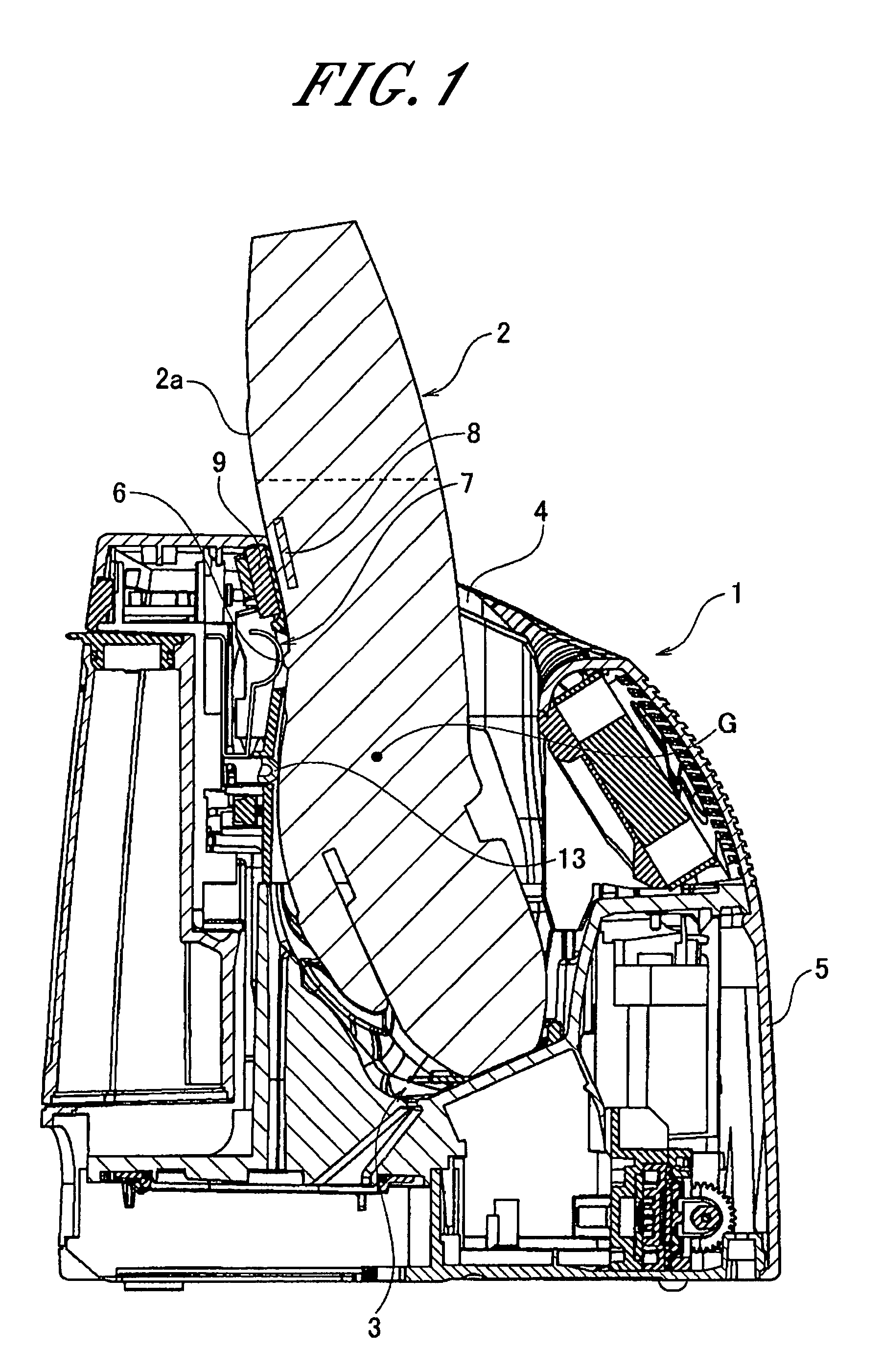
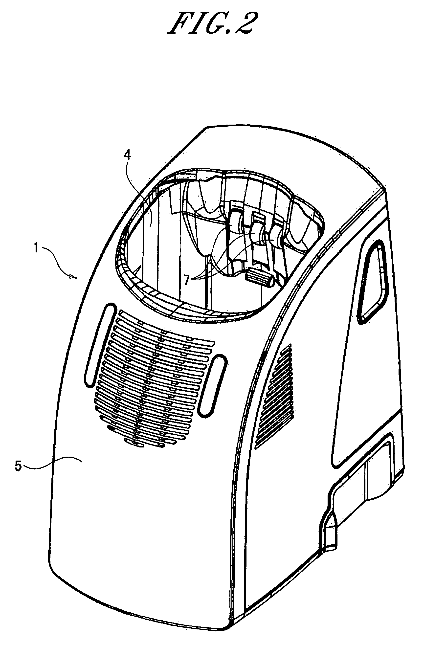
[0027]As shown in FIGS. 1 and 2, a cleaning / charging apparatus 1 includes a cleaning / charging apparatus main body 5 having a shaver insertion opening 4 which is for accommodating an electric shaver 2 to mount the same to a cleaning part 3 in a position where a blade unit of the shaver 2 faces downward. As illustrated in FIGS. 3 and 4, the cleaning / charging apparatus main body 5 has contact metal strips 7 that are electrically connected to terminal pins 6 provided on a rear surface 2a of the electric shaver 2; and a magnet 9 for attracting a metal plate 8 provided inside the...


PUM


Abstract

An engaging structure of an electric shaver and an electric charger is provided wherein the electric charger at least serving to charge the electric shaver is mounted thereat. The engaging structure includes a magnet provided at one of the electric shaver or the electric charger; and an attracting member provided at the other thereof, the attracting member being made of a material magnetically attracted to the magnet. Further, a contact portions for electrically connecting the electric shaver and the electric charger are provided between a weight center of the electric shaver and the magnet disposed above the contact point at an opposite side of a mounting direction of the electric shaver.

Description

FIELD OF THE INVENTION[0001]The present invention relates to an engaging structure of an electric shaver and an electric charger thereof; and, more particularly, to a structure for preventing a loose contact in contact portion for electrically connecting an electric shaver and an electric charger thereof and realizing a stable mounting of the electric shaver.BACKGROUND OF THE INVENTION[0002]In a typical engaging (mounting) structure of an electric shaver and a cleaning / charging apparatus having a cleaning function that is configured to clean a blade unit of the electric shaver, the electric shaver has at its upper portion the blade unit and at its lower portion charging pins which electrically connects the electric shaver with the cleaning / charging apparatus. The electric shaver is placed upside down on the cleaning / charging apparatus so that a shaving head of the electric shaver is mounted faced down. The shaving head is positioned in a cleaning part of the cleaning / charging appara...

Claims


Application Information

Patent Timeline
Patent Type & Authority Patents(United States)
IPC IPC(8): H02J7/00B26B19/38H01R13/639
CPCA45D27/46B26B19/3873B26B19/3833H02J7/0044
Inventor TAKAOKA, YOICHISAGAWA, MASAYUKITANIGUCHI, FUMIOSAITO, ATSUHIRO
Owner MATSUSHITA ELECTRIC WORKS LTD
Learn More