
Pressurized fluidized bed combustor with fuel cell co2 capture

Inactive Publication Date: 2018-11-22
GAS TECH INST
View PDF5 Cites 0 Cited by
  • Summary
  • Abstract
  • Description
  • Claims
  • Application Information

AI Technical Summary

Benefits of technology

The invention combines two types of technology to create a low-cost solution for generating electricity while capturing CO2. The use of pressurized fluidized bed combustors and molten carbonate fuel cells reduces costs associated with the process. The combination of these two technologies significantly improves the state-of-the-art for generating electricity with CO2 capture.

Problems solved by technology

According to DOE analysis, these systems increase the cost of electricity by roughly 75% compared to a coal power plant with no CO2 capture.

Method used


Image

  • Pressurized fluidized bed combustor with fuel cell co2 capture
  • Pressurized fluidized bed combustor with fuel cell co2 capture

Examples


Embodiment Construction

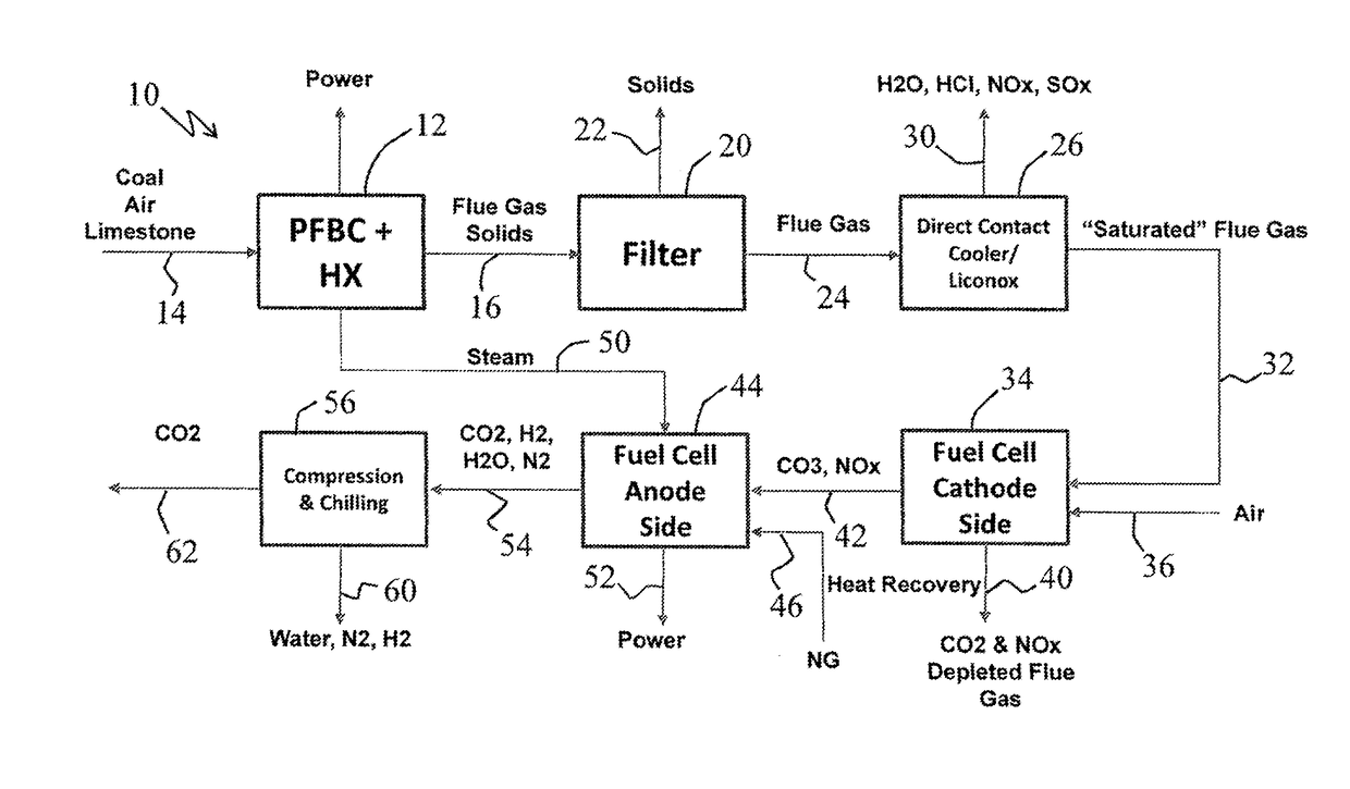
[0014]Combining pressurized fluidized bed combustors (PFBC) with molten carbonate fuel cells (MCFC), as detailed below, desirably provides a low cost solution for electricity generation with CO2 capture.

[0015]More particularly, the incorporation and use of pressurized fluidized bed combustors (PFBC) as herein proposed allows combustion of solid fuel, such as including without unnecessary limitation coal, petcoke, biomass, and the like or combinations thereof, for example, in a compact low cost combustor. In accordance with one preferred embodiment, the PFBC is roughly ⅓ the size of a traditional coal boiler and less than ½ the cost. Although oxygen-fired pressurized fluidized bed combustors such as are currently under development are envisioned for use in the practice of the subject development and are encompassed herein, the subject development is further described below making specific reference to an embodiment that employs air-fired pressurized fluidized bed combustors as benefi...


PUM


Abstract

Systems and methods for generating electrical power combine pressurized fluidized bed combustors (PFBC) and molten carbonate fuel cells (MCFC) to provide a low cost solution for electricity generation with CO2 capture. A solid fuel is introduced fuel into a pressurized fluidized bed combustor to produce steam, a first quantity of electrical power, and a flue gas including CO2. Air, natural gas, at least a portion of the steam and at least a portion of the flue gas including CO2 are introduced to a molten carbonate fuel cell to produce a second quantity of electrical power and an output stream comprising primarily CO2. The pressurized fluidized bed combustor can desirably be air-fired and the solid fuel introduced there into can desirably be in a finely pulverized form.

Description

CROSS REFERENCE TO RELATED APPLICATION(S)[0001]This application claims the benefit of U.S. Provisional patent application Ser. No. 62 / 1507,398, filed on 17 May 2017. The co-pending Provisional Application is hereby incorporated by reference herein in its entirety and is made a part hereof, including but not limited to those portions which specifically appear hereinafter.[0002]The subject matter of this application is also related to prior U.S. Provisional Patent Application Ser. No. 61 / 184,367, filed on 5 Jun. 2009; prior U.S. Provisional Patent Application Ser. No. 61 / 184,384, filed on 5 Jun. 2009; prior U.S. Provisional Patent Application Ser. No. 61 / 184,382, filed on 5 Jun. 2009; prior U.S. Provisional Patent Application Ser. No. 61 / 184,383, filed on 5 Jun. 2009; prior U.S. patent application Ser. No. 12 / 794,218, filed on 4 Jun. 2010, now U.S. Pat. No. 9,567,876, issued 14 Feb. 2017; and prior U.S. patent application Ser. No. 15 / 085,113, filed on 30 Mar. 2016, now U.S. Pat. No. 9...

Claims


Application Information

Patent Timeline
IPC IPC(8): F23C10/16H01M8/14H01M8/0612H01M8/0662F23C10/00F23J15/02
CPCF23C10/16H01M8/145H01M8/0643H01M8/0675H01M8/0687F23C10/002F23J15/025H01M2008/147F23J15/006Y02E60/50F23C2900/10006F23J2215/50F23J2900/15061
Inventor FOLLETT, WILLIAM W.
Owner GAS TECH INST
Learn More