
Microfluidic chip, microfluidic device, associated uses and methods

Pending Publication Date: 2018-11-22
UNIV DE ZARAGOZA +2
View PDF3 Cites 2 Cited by
  • Summary
  • Abstract
  • Description
  • Claims
  • Application Information

AI Technical Summary

Benefits of technology

The present invention focuses on creating microfluidic chips that are highly advanced in terms of their size. These chips also allow for the effective operation of microfluidic valves and pumps.

Problems solved by technology

Although said systems allow the construction of valve systems on microfluidic chips, they all possess a severe limitation in regard to the minimum size that they can reach, because their fabrication methods are not effective for producing chips with culture housings with dimensions smaller than 1 mm, which also allow a large number of said housings to be made in the chips (thus favoring mass production of the chips).
On the other hand, with respect to the techniques of the implementation of actuator systems for known microfluidic chips, these also pose a limitation in regard to the minimum size of said actuators, which in practice means that, as a result of the minimum separation that must be maintained between consecutive actuators, devices are produced with an excessive volume of conduits and chambers, which requires the disposable element of the chip to be larger, which increases the economic cost of said disposable element, also requiring the use of larger quantities of fluid, and increasing the probability of the appearance of air bubbles, which are incompatible with the testing of live cells.
In addition, the known systems have little or no flexibility in the configuration of the internal distribution of the conduits and micro-chambers in the chip, due to the need to use molds for the fabrication of the disposable part, making it very costly to modify the design, as well as the number, of the internal connections between micro-chambers, inlets and outlets in the chip.

Method used


Image

  • Microfluidic chip, microfluidic device, associated uses and methods
  • Microfluidic chip, microfluidic device, associated uses and methods
  • Microfluidic chip, microfluidic device, associated uses and methods

Examples


Embodiment Construction

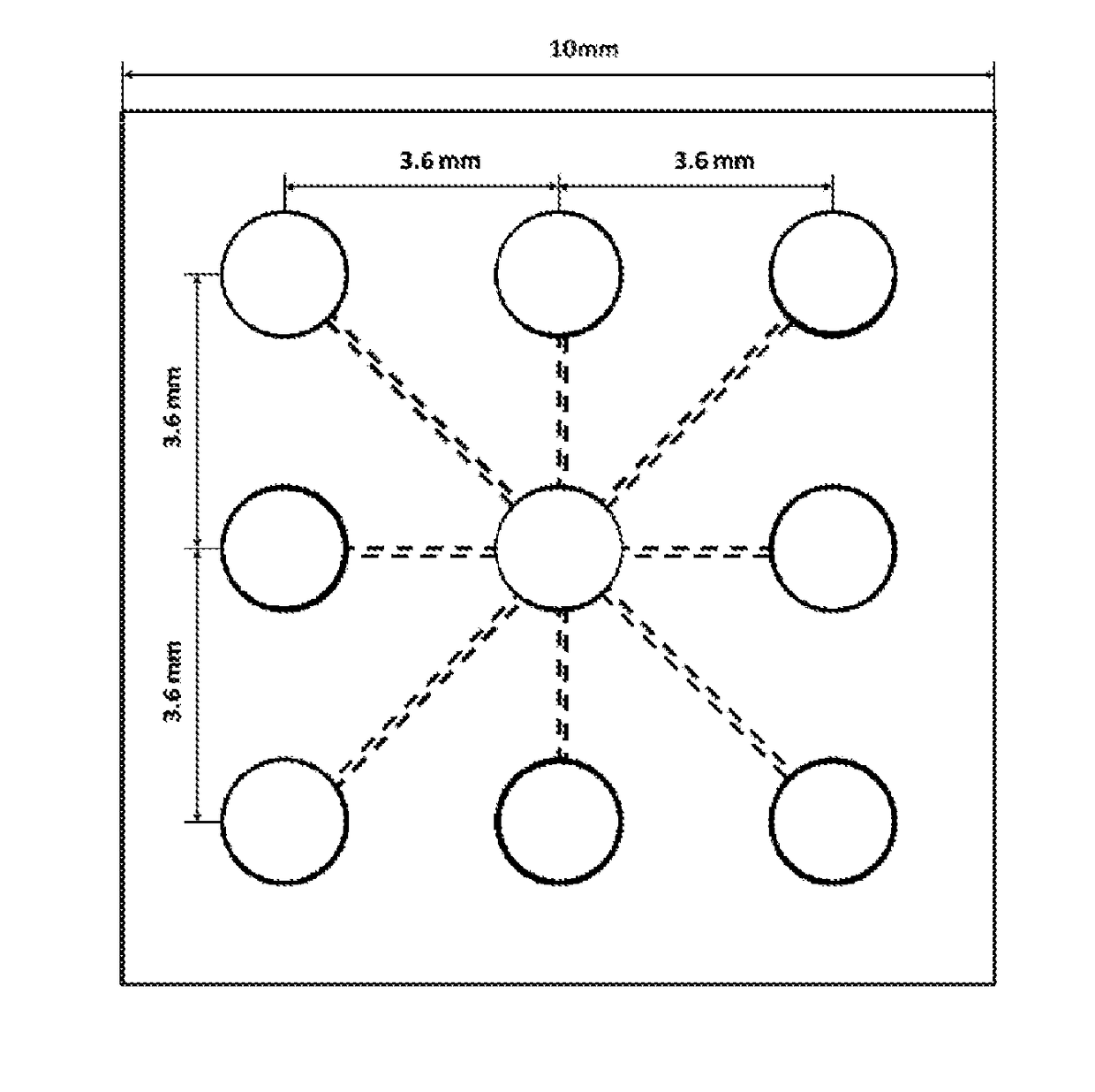
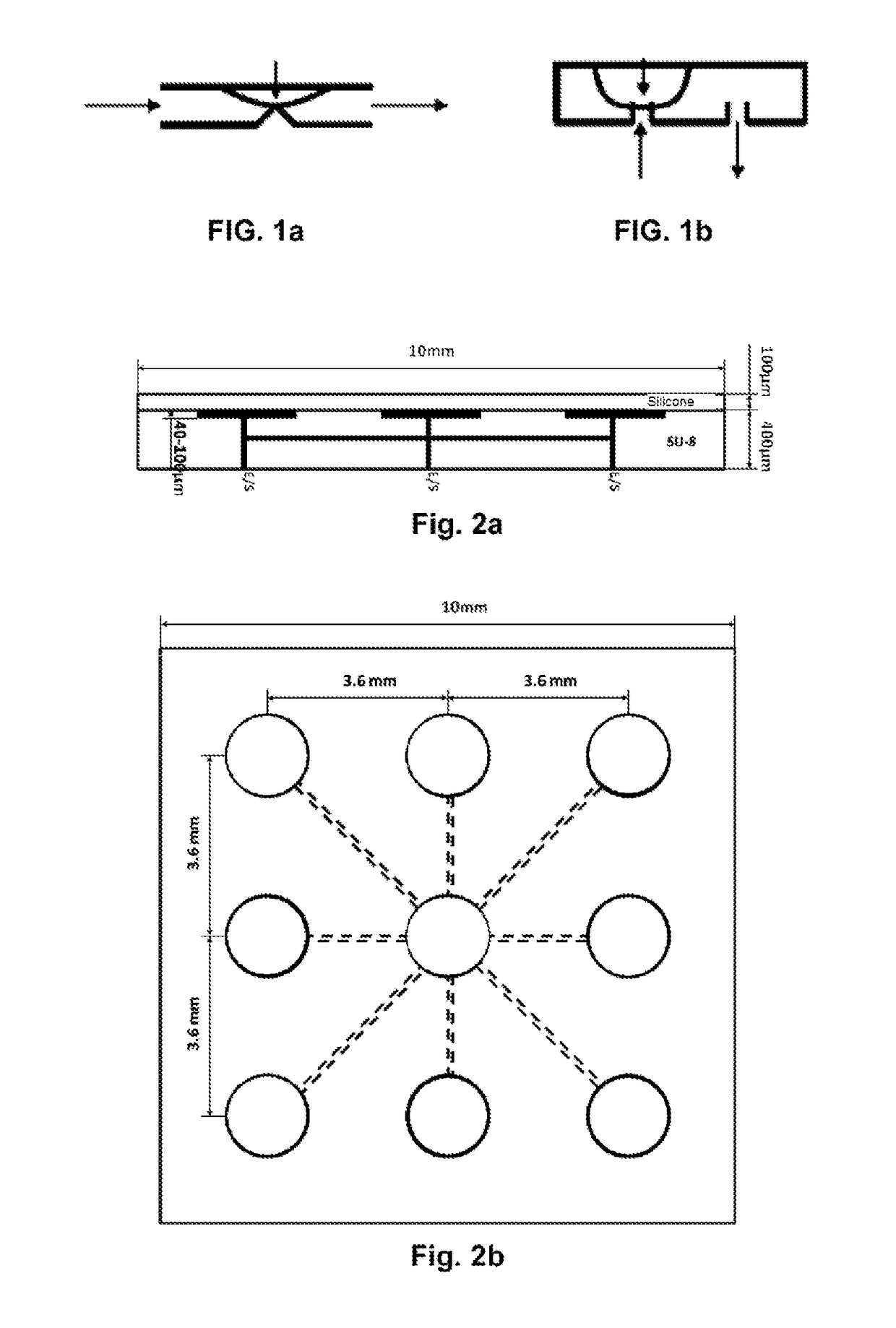
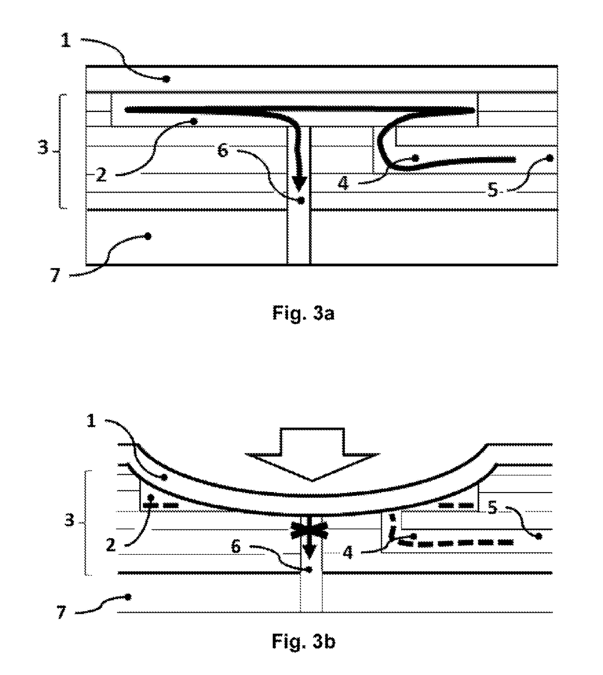
[0058]As described in preceding paragraphs, one object of the present invention relates to a microfluidic chip especially intended for the study and culturing of cell samples, to which end it comprises means for housing said samples, as well as a plurality of microfluidic channels for the circulation of fluids (for example, for the feeding of the housed samples). In this sense, the microfluidic chip of the invention comprises a principal structure formed by a succession of one or several micro-structured layers (3) arranged on a base substrate (7). The structure of the micro-structured layer or layers (3) makes up a network of micro-chambers (2) and microfluidic channels (4), as well as fluidic inlets (5) and outlets (6), through which both the live cells to be studied and the fluids that will circulate through the microfluidic circuit can be introduced. The base substrate (7) may be manufactured by means of machining, deposition, or stratification.

[0059]The plurality of microstruct...


PUM

PropertyMeasurementUnit
Temperatureaaaaaaaaaa
Pressureaaaaaaaaaa

Abstract

The present invention relates to a chip equipped with a plurality of compact microfluidic valves with multiple inlets and outlets, actuated by means of a flexible membrane system. The chip preferably comprises a deformable sealing layer made of at least one flexible, elastic, and insulating material; a structure formed by a succession of one or several microstructured layers, wherein said structure comprises one or several micro-chambers, one or several microfluidic channels, and one or several fluidic inlets and outlets; and wherein said structure is installed on a base substrate. The invention likewise relates to a microfluidic device that comprises the aforementioned chip, to a method for the fabrication of the chip, and to the uses associated with the chip and the microfluidic device.

Description

FIELD OF THE INVENTION[0001]The present invention falls within the technical field corresponding to microfluidic devices for the culturing of cell samples, with said devices known as “laboratories on a chip”. More specifically, the invention relates to a chip equipped with a plurality of compact microfluidic valves with multiple inlets and outlets that can be actuated by means of a flexible membrane system. The invention likewise relates to a microfluidic device that comprises the aforementioned chip, a method for the fabrication of the chip, and the uses associated with the chip.BACKGROUND OF THE INVENTION[0002]The existence of a large number of “laboratory on a chip” systems for the culturing of cell samples is currently known. The different applications of these systems include the implementation of microfluidic membrane valves or pumps, based on chips on which an elastomer layer is deposited, covering one or more housings or chambers, whose volume is modified by means of the app...

Claims


Application Information

Patent Timeline
IPC IPC(8): B01L3/00B32B3/30B32B38/00B32B25/08B32B37/18
CPCB01L3/502707B01L3/502738B32B3/30B32B38/0008B32B25/08B32B37/182B01L2300/123B01L2200/027B01L2300/043B01L2400/06B01L2400/0484B01L2200/12B01L2200/0689B01L3/00B32B37/16B01L3/502715B01L9/50F16K99/0015F16K99/0048B01L2400/0638B01L2400/0655F16K2099/0084
Inventor FERN NDEZ LEDESMA, LUIS JOSEMONGE PRIETO, ROSA MARIACALAVIA CALVO, JOSE LUISSANTOLARIA MAZO, JORGEOR S PONTAQUE, JAVIERPERIB NEZ SUBRIRON, CARLOSRODRIGUEZ FORT N, JOSE MANUELOCHOA GARRIDO, IGNACIO
Owner UNIV DE ZARAGOZA
Learn More